 For his masters at Cornell, [Christopher McNally] designed a simple, non intrusive home power meter capable of doing everything a ‘smart meter’ can do – log power consumption throughout a home, and display a log of a home’s power consumption over WiFi. He’s even testing out some interesting ideas, like automatically detecting when specific devices turn on by reading the current data.
From [Chris]'[Jeramy] developed his system around the Arduino and a Ethernet shield, taking care of networking and choosing a micro, leaving him more time to develop the more interesting part of the project: sensing current. For this he used a small, clip-on current transducer. This sensor generates up to 10 VAC across a resistor, but the Arduino doesn’t play well with AC, requiring a small rectifier built around an op amp.
While the project works as a homebrew smart meter, [Jeramy] wasn’t able to automatically detect when certain devices were powered on. This is partly due to the fact that changes in current were only seen in magnitude and not waveform. Also, if two devices were powered on at the same time, the software would see that as a larger device that draws the sum of the current of two smaller devices. Still, [Jeramy] came up with a cheap way of metering power in any home, and the cost of his solution is cheaper than a lot of professional systems out there.
All the code, files, and design report are available on [Jeramy]’ git.


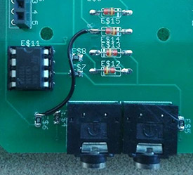
Those 3.5 mm jacks are used for plugging in the transformers?
Yes, I just uploaded a pic of the board in service. The voltage across the jacks is relatively low (I measured ~36vac but i didn’t have much of a load on it), but the two terminals are also so close together that if you touch them you shouldn’t feel a shock. That said, I recommend holding it by the plastic part.
I did this because the transformers from seeedstudio come this way, and it was easier to model mine after it than change theirs.
“[Chris] wasn’t able to automatically detect when certain devices were powered on. This is partly due to the fact that changes in current were only seen in magnitude and not waveform. Also, if two devices were powered on at the same time, the software would see that as a larger device that draws the sum of the current of two smaller devices”
In the literature this is referred to as disambiguation – there is quite a substantial volume of work around it.
e.g. https://www.vs.inf.ethz.ch/publ/papers/beckel-2012-improv-sigbed.pdf
However, a larger flaw in his meter is potentially (see what I did there?) not taking into account the line voltage and phase to allow for accurate calculation of power factor.
I’ve been always asking myself how feasible are those “clip based current transducer” meters. It seems like they are easy to use with arduinos, cheap and everything.
But as you say, without taking into acount line voltage and phase… it seems to be very error prone. Does somebody know any report that throws some light on “how big the error is”? I mean, some average measures compared to a “Real” meter. Of course it will depend on how many inductive power are you connecting to the line and so on, but I’ve never seen any clear conclussions.
It is fairly easy to calculate the margin of error if you can identify the power factor of the devices – the clamp assumes a PF of 1 (unless the software applies some correction factor as s fudge). It is quite possible, for example, for a switch mode power supply to record a current-clamp consumption of say 15-20W when actually consuming only 1W-2W.
It has nothing to do with the sensor itself being in accurate. The data is lost when the AC is converted to DC and filtered. He would have had to do something like create a low voltage AC signal with a DC bias so he could read it with the A/D on the Arduino. Then compare that signal to a reduced line voltage signal in the same way.
I think people here need to check out open energy monitor. It also monitors voltage so you can get a fairly accurate reading.
Neat project and I am glad to see they are accepting technical thesis for masters.. when I did mine the department chair told me mine would likely be the last technical (as opposed to theoretical) thesis they would take as they were being pushed that way by the accreditation agency. At the masters level I do not think that was for the best.
The attempt to profile what appliances are running was interesting. With house knowledge and a fine enough scan rate I would have thought it possible to determine if two small devices turned on as opposed to one large one, the small devices would seldom turn on at exactly the same time. It would be fun to see Chris’s research on this.
With a cheap method of monitoring current it does bring up another thought though. There are certain appliances in the home (such as sump pumps) that should be fairly consistent in their current usage when they operate. As they begin to fail that usage is likely to change, in the case of the sump pump likely increasing. I am thinking it would be possible to monitor the usage and make a guess when to flag the owner that the appliance is about to fail. In the case of the sump pump that would mean a replacement before the basement floods. Might need to play with this.
And a word of caution. CTs are a 1:(very large number) transformer so can produce lethal voltages and / or self destruct if placed on the conductor without a loading resistor present. Be careful.
What I wanted to do for the voltage reading is use the circuit here – http://hackaday.com/2014/04/24/diy-multimeter-arduino-sold-seperately/ – and disassemble a pair of circuit breakers so that they can be snapped into the breaker box. I have been looking to build my own switching power supply as well, so hopefully they can read voltage as well as supply it.
The kids at Cornell have another great solution too.
https://instruct1.cit.cornell.edu/courses/ee476/FinalProjects/s2008/cj72_xg37/cj72_xg37/index.html
We used a capacitive coupler and 1:1 transformer to inject some m sequences at 30MHz. We did correlations to help with dissambiguations as far as which device was turned on… at my old school.
Isn’t this almost exactly what the Open Energy Monitor Project is?
http://openenergymonitor.org/emon/
Yes it is. In the same spirit that T-Mobile and Verizon provide almost exactly the same service.
Also, v2 of this board has similarities to the main board of the growerbot ( http://www.growerbot.com/ ) which I discovered when I went back to my Make Magazine v18 ( http://makezine.com/projects/make-18/garduino-geek-gardening/ ) because I wanted to make the circuit design as versatile as is practical, and did a “where are they now” search. But, so far as that goes, it is probably possible to find several projects that are almost exactly the same. I feel that the difference is that they have covered more ground, but it is still not the solution for me.