[Sugapes] always wanted to cut a few corners and build a really, really cheap 3D printer, but the idea of using linear actuators – pricing them, sourcing them, and the inevitable problems associated with them – scared him away. One day, he realized that moving in a plane in the X and Y dimensions wasn’t hard at all; cars and robots do this every day. Instead of moving a 3D printer bed around with rods and pulleys, [Sugapes] is moving his 3D printer around with wheels. It’s different, it’s interesting, and it’s the perfect project to show of his creativity for The Hackaday Prize.
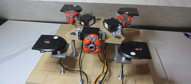
The drive system [Sugapes] is using is called a holonomic drive system. In his build, three omnidirectional wheels are attached to continuous rotation servos, each of them mounted 120 degrees apart. The print bed is simply placed on these wheels, and with the right control algorithms, [Sugapes] can move the bed in the X and Y axes. With an extruder on a Z axis above the bed, this setup becomes a 3D printer with a theoretically unlimited XY build axis. Pretty clever, huh?
There are a few problems [Sugapes] will have to overcome to turn this project into a proper printer. The omnidirectional wheels aren’t the best at transferring movement to the bed, so a quartet of USB optical computer mice are being used for a closed loop system. [Sugapes] put up a video of his project, you can check that out below.
![]() The project featured in this post is an entry in The Hackaday Prize. Build something awesome and win a trip to space or hundreds of other prizes.
The project featured in this post is an entry in The Hackaday Prize. Build something awesome and win a trip to space or hundreds of other prizes.


I wake up in the morning. I see the yellow sun. I see the green grass and I think to myself, I hope it will be a pink day.
I wake up in the morning, I eat a yellow banana, a green pepper and in the evening I watch the pink panther on TV.
I wake up in the morning, I hear the phone “green green”, I “pink” up the phone and I say “Yellow”
This is cool but… is it practical? Getting a reasonable precision could be hard.
Replace servos with steppers. Replace red-led mice with laser mice. Replace bulky toy omniwheels with high precision ones.
???
Profit!
When you find yourself typing “cool, but not practical” you should stop before you hit “Post”: you’ve found the real reason why the hack was made, then discarded it for an incorrect one.
I think you misunderstood me, I’m not at all complaining. More wondering if it could be a practical solution or if it’s doomed to “just” being a cool hack.
Mouse sensors can have >4000 dpi resolution however repeatability etc. are unknown to me.
Haha, my bad! I’m so used to the “this is useless why would you ever do it >:[” posts that when I see a comment superficially resembling such a post my eye muscles start twitching just from conditioning.
Excited to see where this one goes. Definitely a novel approach!
He’s definetly onto something!
The wheels would run over every layer of your print… this is clever but not practical
The first part of the video just showed that the wheel arrangement can produce controlled motion, then he flipped it over and put a cardboard platform on the now-stationary wheel assembly. In use, the wheels are not running over the platform.
Maybe moving the print head rather than the build platform could be a workable idea though. What if the print head was held to a metal ceiling with magnets? Z movement could be achieved by either extending or retracting the print head or by moving the “ceiling” that it drives on.
I chuckled when he demonstrated the Z-Axis by moving it X and Y.
I don’t think the excuse to build “cheap” is really applicable here. Threaded and smoothed rods are not expensive and steppers can often be found much cheaper than decent servos. Those meccano wheels are not cheap. Unless he had the mice laying around, those are likely $10-15 a pop. An arduino for the servo control? $30 if he bought a prepackaged one.
Then of course, in the end, he will need to write completely custom software to control everything from gcode. And in the end, the precision will be nowhere near even the cheapest of printers.
Novel? Yes. Cheaper? That’s really not (or shouldn’t be) a design goal here.
Hackers often start out a project thinking it will be cheaper if they build themselves, and it feels cheaper because they are buying parts a little at a time. But when you add it all up, especially add all the parts you thought you would need but didn’t work out, etc… I have very few projects that actually turned out cheaper.
Depends on where you live, actually. If you’re lucky enough to live near a Micro Center, you can get optical mice of the el cheapo brand for around $3-5 a pop, an off-brand but good quality and from official schematics Arduino Mega for $20 (as opposed to a normal with less pins), and I believe they may have decent continuous servos fairly cheaply, too. Fry’s Electronics has the mice, and possibly the servos, but I have yet to find an Arduino of ANY kind there. It’s only expensive for most of that stuff if you go to a place like Radio Shack which tends to be a bit overpriced compared to the big-box-type electronics stores.
Meccanum wheel! That’s the word I was looking for!
A few years ago someone on here 3D printed a set of those, too. Tho they were a bit plasticky and crappy, better for scrabbling round a dusty moon than accurately anything. Optical feedback is only any good if the mechanics are *capable* of the accuracy you want, or else the platform’s just gonna be sliding around forever.
Maybe rubber coating them would help a bit. But fundamentally I don’t think Meccanums can do it. The roller axles spinning round the main axle will just have too much play for mm accuracy.
Anyway nice principle. I think for cheap though the deltas using fishing line are probably the way. Or else, someone hacking up old cellphone screens to UV tubes, cobbling a LOT of second-hand virtually-free stuff together. Garbage-based 3D printers may be a revolution for engineering in poor countries. For light plastic at least, prob still need real tools for working metal.
Just rubber coating them isn’t enough. The build platform needs to be of enough weight to provide enough friction in order to not slip. And of course, everything had better be perfectly level or you are going to have skipping.
Also, I am fairly certain that even though a servo has 1 degree resolution, the repeatability of position (not mention that servos jitter which is not a good thing when trying to print) is not likely to be a guarantee. It is not really intended for that.
Finally, a standard continuous rotation servo has the pot removed, so there is no angular resolution. He doesn’t really need continuous rotation here since the build platform is a definite size. Gearing the servo output would be better. But then… why not just use steppers?
I believe the mice are there to sense the bed position itself, so I guess the servos are just being used as geared down DC motors.
And yeah, Meccanum. lol Silly me.
I needed your wrong one to start me remembering what they’re actually called. Team effort!
You do realize that these are not, in fact, Meccanum wheels, right? The Meccanum drive-train is also holonomic, but it operates on a principle related to, but different from, the one in the article. The rollers on its wheels are angled, so that part of the rotation force is turned into a lateral thrust. They must be used in pairs to allow standard forward/backward travel by canceling this lateral thrust. The one in the article is a Kiwi drive, which is related to the Killough platform.
Runnerpack, no. I was not aware. Thanks for the correction!
Actually, [justice099], that reply was directed at [Greenaum], but I’m glad to have helped.
Ah right, didn’t know that, was working on Justice’s assumption, plus they look like Meccanums. Except in the latter case the rollers are diagonal, so I wasn’t paying attention. It’s been a while since I read up on them, and yep they have to work in pairs, there was a good HAD article on them a while back.
Ta for pointing out what they actually are though, off to look up Kiwi drives!
Apparently Kiwi Drive is a very desirable street in Derbyshire. And a 2-line explanation on one robot website. Any good pointers? Nice and simple if possible, it’s early in the morning!
It’s an interesting idea to get a large, variable sized build platform. I could also see it being cheap, allow for a variety of materials and could allow it to be bonded with the print to become part of the final object (so you don’t necessarily need a raft). For large objects using an extruder with a low resolution, this might be a reasonable system.
you need better parts acquisition channels. chinese online retailers have everything for dirt cheap. $2 shipped per mouse, $10 or less for a knockoff arduino. not sure about the wheels but I have a feeling there are ebay versions for cheap.
The economy of scale is the same for the other parts I mentioned. We go to China, then those parts are still cheaper.
It’s not like China doesn’t make them too.
In the end I don’t expect this endeavor to be cheap either (I am the designer). My main motivation here is learning. Cheap is just a design constraint to make the problem even more interesting. Since I expect many more iterations I will end up buying much more parts than those that will actually be present in the final design. I hope however that the final design ends up cheap enough to make it interesting for others to reproduce it, and even improve on it…
.. the idea is an interesting one, and mechanically just that little bit different. Furthermore I can see that it is possible to extend this to allow rotation of the build area. The lack of precise control would be an issue, but I can see further ideas developing from this one…
Thinking about it, and “extension”… and my previous post… perhaps this would be useful for a cement-based printer. Something on a scale where the accuracy is proportionally good enough. Or if not cement, maybe chocolate, with accuracy that’s good enough and much better speed than the plastic-based extruder models.
Wonder if Meccanum wheels cope with cement dust? With a big enough platform and some curtains about, might not need to.
Closed loop control schemes are always a good choice in my opinion, but I imagine it will still be susceptible to accumulated error as this is only closing the loop on incremental movements. Regardless, the real work will be in the control algorithm. Excited to see how this turns out.
I remember using optical mice for positioning… the cumulative error will be HUGE
I agree. Better to use a cheap webcam and a fiducial marker system like this router: http://www.youtube.com/watch?v=-UmL7xZZSUk
Why not use a combination? Optical mouse sensors for a closed loop system for the drive and optical markers underneath the platform for “absolute” positioning of the platform. The mouse sensors should be more precise for small movements after all…
(Beginning to wonder if this can’t be made practical after all ;)
I forgot to link to a fiducial tracking system :P
http://sourceforge.net/projects/reactivision/
Does anyone even make hobby sized servos with greater than 1 degree of positional accuracy?
Loving the concept, especially since the bed isn’t attached to anything, makes it easy to just pick the bed up and put a new one on!
I don’t think the project is practical but it is a nice experiment indeed, also combining the mouse sensor data to have a certain degree of close loop control is quite interesting. Regarding the problems arising from the use of cheap badly made omniwheels. People seem to stick to the same type of omniwheels all the time but the truth is there are alternatives and in some cases they may be easier to manufacture to be precise. Here’s an example: http://imgur.com/fGsgGjP
That omniwheel is pure genius!
That looks like one of Killough‘s wheels, but the labels are in Catalan… Where is this from?
Not cool to answer a question THREE years late. I didn’t know about the Killough’s invention and it is certainly the same wheel. I learned about this wheel from a professor in my university who built a similar platform in the early 2000s (http://t.co/lBhvW8mmPj), I’m kind of disappointed because I thought it was him who invented this wheel.
Is anyone else getting tired of the HaD ‘editors’ essentially taking a write-up that someone put real time into, splicing in a few lines to make it look like they thought about the posting, and hosting it here? C’mon guys, you’re better than that. Have an opinion, write something of your own.
ummm…it was a submission to their contests.
*blink* *blink*
Try a V8 or a snickers.
I love the concept as I also built an holonomic robot. I also try to work with mice and … it don’t work at all. Old mice got serious friction issues and for digital mice, it’s a false good idea. Remember that with optical mice it’s You (the user) that closes the loop. Moreover optical mouse got acceleration treatment and accuracy depends on speed. You should find other way to closed your loops (omnywheel odometers, floating measuring rods, IMU…)
Good luck.
Isn’t the acceleration of mice a driver issue? Or at least an option you could tell the mouse to adjust, or indeed stop? There’s the option of going straight to the optical sensor as some have done.
Perhaps a few cameras focussed on a small pattern each could be used to track movement well enough. Or even just stripey strips.
Your point about the user being part of the loop may well be more important than people realise, there’s all sorts of levels of adjustment, entraining, and compensation being done in the human sensorimotor system. From the vision system, through the brain, all the way to the muscles, every bit of it learns and controls. It makes us a difficult part to put in or take out of a system.
If the mice are being used to sense the position of the bed itself (I couldn’t watch the video with the audio on) like I think, there are numerous, more accurate ways to do that. As you mentioned, a vision system that simply tracked a square (the build platform) would be simple enough to implement.
And if you wanted to maintain the “indefinite” factor, track a square within a larger square until that section is complete, then begin a new square.
No, it’s inside the mice chip. Maybe it’s possible to stop it but I don’t know how.
My tries were with old optical mices with an optical chip + USB chip and I only use the first one with µC. Recent mice are reduced to only one chip, hacking is really hard (except with embedded computer like raspberry)
(Strangely enough) I actually stand by my design choice of using some sort of optical feedback system! :-) I really feel this is the option that makes more sense for the kind of problem I am trying to solve. Of course the optical mouse sensor is not the better adapted one to this kind of job since its design constraints are much different (e.g. low cost, small size, etc.). I am using them mostly because they are easy to source, and to interface with, but the price to pay is that I have to overcome their inherent inaccuracies. Ideally I would use a single higher resolution camera instead (typical optical mice cameras only have 16×16 pixels resolution), and devise my own optical flow algorithm to do basically the same thing as the mouse does, but better. However that is a completely different challenge to tackle (i.e. a much more brainier one). Maybe someone out there is up to that challenge?! ;-)
I don’t understand why there are three motors?
It may could be possible to control x and y with 2 motorized wheels and two non driven.
…With three motors it’s possible to rotate the platform. Got it.
Well, one thing I don’t see anyone has mentioned:
“With an extruder on a Z axis above the bed, this setup becomes a 3D printer with a theoretically unlimited XY build axis.”
I assume it’s suggested this is accomplished by just enlarging the bed? Well, there are constraints to that:
1) To avoid running off the supports (mice), no edge of the bed may move INSIDE the square defined by the four supports.
2) To avoid the bed tipping over, the overall center of gravity of the bed must never fall OUTSIDE the same square; and should avoid being NEAR it.
Meaning that If you want for example one square foot of printing area, you’d need maybe a bed 3 feet on a side (9 sq. feet) to ensure good stability. Plus another 6″ clearance on all sides to allow free movement, so 16 sq. feet of desk real estate required to support 1 sq. foot of printing area. Ouch…
And don’t forget that 9 sq. foot bed must be rigid enough not to sag or flex under its own weight.
Well… kind of correct, however if the build platform sits on a ball roller bed … think something on these lines ..
(http://www.woodcraft.com/Images/products/600/07B08.jpg) … then you can drive a very large build area, perhaps not infinite, but certainly not as small as you are suggesting.
Or mount the wheels on the bed, put the wheels side on the floor and print on top side.
Alternatively you could use an omnidirectional treadmill as a starting point for the base:
https://www.youtube.com/watch?v=q97QxnLlDcI
That way you have as much build area as floor space devoted to it. Plus it’s possible to add a tilt axis to the bed.
i was wondering how stable this will be .
Wihout having solid connected parts you will have so much slippage on the print but on the steps too due to the friction …
Also not to mention the weight of the nozllehead+extruder that will add to all this .
Just some concerns nothing more .
Keep going !!!
The weight of the print head would not bear on the platform, or mechanism that drives the platform if this device stands a chance of working at all. The print head would have to be attached to some kind of a boom arrangement, and be suspended over the work platform.
It works great as long as you’re willing to hold the platform up with your hand.
The 3 funny wheels? It’s OK. This is elegant though
https://www.youtube.com/watch?v=9rcU5z3nyWk
I’m curious how much z-axis deviation there is as the “wheels” rotate: certainly too much for typical plastic extrusion, but probably fine for the aforementioned suggestions of cement etc.
I realized I needed a base for the molding of the deer.