
In the “Say It with Me” series, we’ll take a commonly used concept out of electronics and explain it the best we can. If there’s something that’s been bugging you, or a certain term or concept that keeps cropping up in your projects, let us know. We’ll write about it!
What’s up with input impedance? You hear people talking about it, but why does it matter? And impedance matching? Let’s break it all down.
First of all, impedance is the frequency-dependent sister of resistance, so for intuition we’ll first work through the cases of purely resistive impedance. And that’s almost fine if you’re only ever working at one frequency. We’ll hint at the full-blown impedance = resistance + reactance version at the end, but it’s really its own topic. For now, pretend that your circuits aren’t reactive.
Input and Output Impedance
If we’re going to talk about input impedance we need to look back at our old friend Ohm’s Law. (If there’s another equation that’s as useful as Ohm’s Law, we don’t know it.) V=IR. Or, solved for current, I = V/R. What Ohm’s law says, in words, is that the amount of electrical current flowing in a circuit increases as you increase the voltage, and decreases as you increase the resistance. It’s that simple, but it’s really powerful.
If you want one more amp of current to flow through the circuit, you’ll need to increase the voltage by R volts. Or if we increase the voltage by one volt, we’ll increase the current flowing through the circuit by 1/R amps. Thanks, Georg Ohm.
Now think of an electronic component. It doesn’t really matter what, so we’ll think of an amplifier here. Imagine that we want 3.5 V, for whatever purpose, to show up on the input to our amplifier. You’d think it’d be easy, just hook up a wire to the amplifier and put 3.5 V on it. That’s not the whole story.
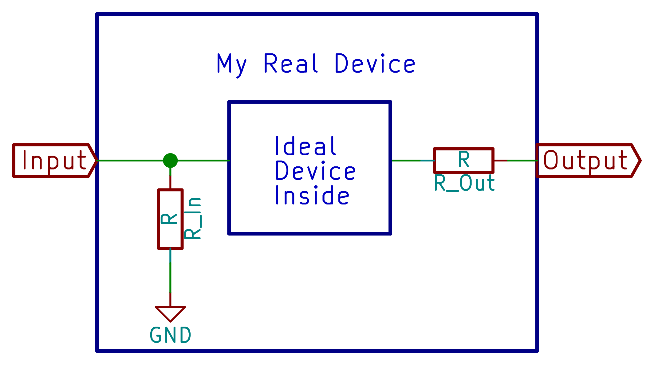
Engineers like to think of devices like amplifiers as simply reading the voltage level at their input. But we’ve got a real amplifier, and it takes some current flowing in for it to work. The compromise, then, is to think of the real amplifier as being an “ideal device” inside, with a resistor to ground that sucks in some current from the input. The value of this imaginary input resistor is the device’s input impedance.
So when we put 3.5 V on the input of the real device, some current flows into the resistor and out to ground, and this can in turn lower the voltage that reaches the ideal device that lies inside.
Similarly, the chip isn’t able to put out infinite amounts of current at any given voltage. (That would be cool, though, no?) Instead, as we ask for more and more current from the device, we’ll see its output voltage sag. Just like with input impedance, we can model this sagging as a simple resistance: how much does the voltage drop when we ask for more current output? V=IR. Again, the output impedance is that output resistor’s value.
Both input and output impedance are quantities that you can often look up in the datasheets of a single component, figure out yourself for a transistor amplifier circuit, or even measure yourself.
Impedance Matching
Now you’ve got the idea behind input and output impedance, and we’re ready to think about impedance matching. Roughly speaking, there are three cases. The first is where you care about getting a voltage signal from one device to the next, and you’re running everything at lowish frequencies. Case two is where you’re interested in transferring electrical power (voltage times current) to the second device. Case three is a catch-all for when you’re working at high frequencies and need to minimize reflected signals.
Voltage Transfer: High Impedance Bridging
If you’ve got a low-frequency voltage signal, you don’t actually want to match impedances at all. Instead, and this goes for basically all audio signals, you want a low output impedance and a high input impedance.
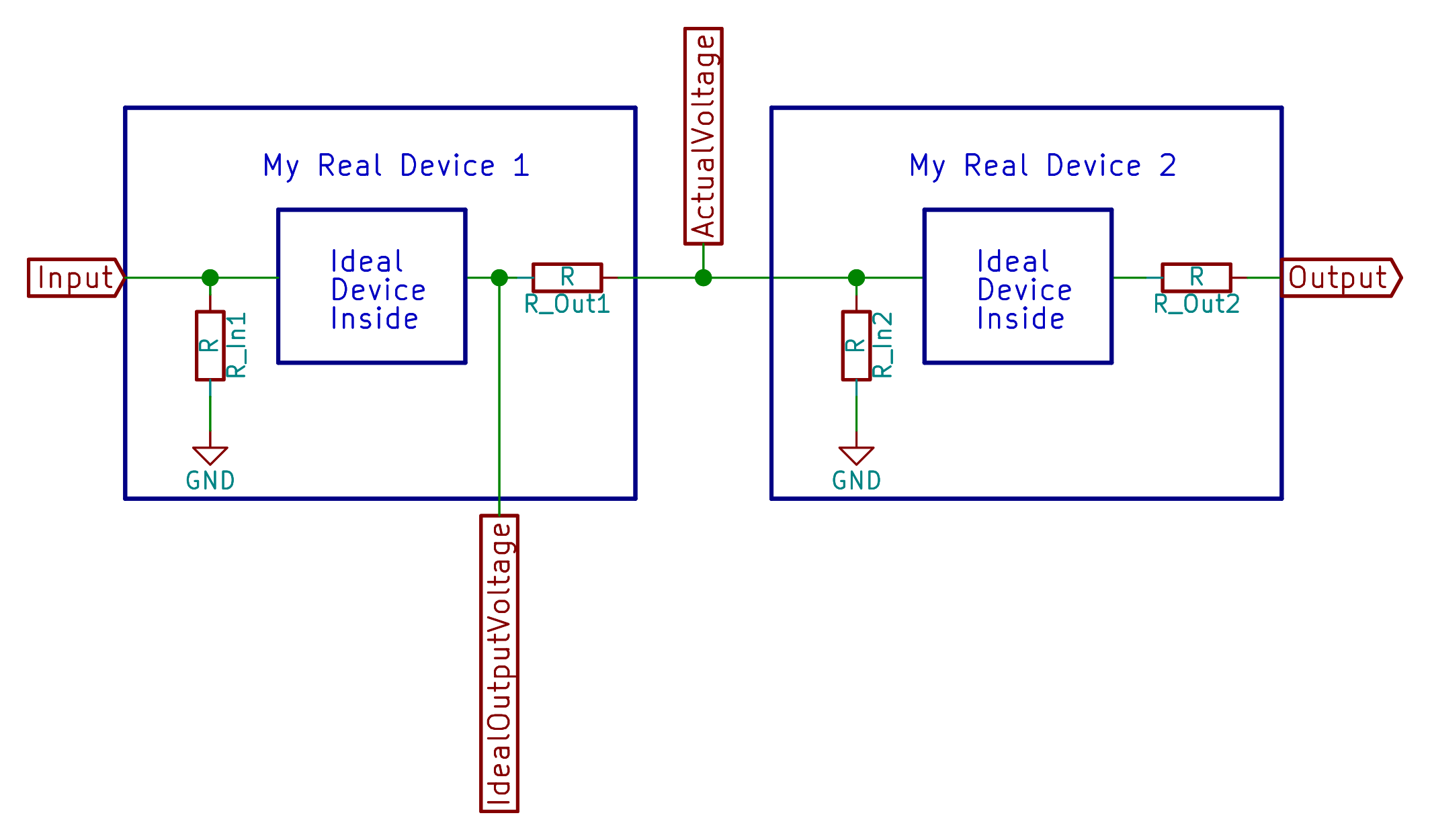 To see why, we’ll look at the circuit diagram. Between the two ideal amplifier stages, we’ve got a pair of resistors forming a voltage divider: the output impedance of the first stage and the input impedance of the second. What this means is that the voltage that the second amplifier sees is a scaled-down version of the output from the first amplifier.
As a concrete example, say we have 1K output impedance on the first amplifier and 100K input impedance on the second — a very desirable case. If the voltage leaving the first ideal amplifier is 3.5V, the voltage arriving at the second amplifier is 3.5V * 100K / (1K+100K) = 3.465 V, just about one percent off the original value. Close enough for jazz.
Now assume we’ve got 10K output impedance and 10K input impedance. The voltage that reaches the second amplifier is 3.5V * 10K / (10K + 10K) = 1.75V. In short, half of what we naively thought we were getting. That’s not good if we care about the analog voltage level.
Taking this voltage drop that arises from input/output impedance into account all the time is a pain, and as we can see, it’s minimized when the output impedance of the first amplifier is small, and the input impedance of the second is very high. So to make our life easy as designers, we just look for parts with low output impedance and high input impedance and pretend that the whole problem doesn’t exist. Horowitz and Hill (2nd Edition, p. 65) suggest a factor of ten between input impedance and output impedance. For critical voltage-dependent analog circuits, more is better.
Before we leave this topic, note that relatively little current needs to flow through this system to get the voltage signal across if we have a high input impedance.
Power Transfer
Now what if the second device is something like a motor or antenna? Our goal is not to put a certain voltage on the second device’s input, but rather to transfer as much power to it as possible.
To transfer maximum power you want to have the same input impedance on the second stage as you have on the output of the first. (You always want lower output impedance on the first device — more current sourcing capability is always better, but once you’ve hit that limit, you match the input impedance of the second to it.) Why? Here’s a graph where the voltage is set to 5V and the output impedance of the first device is 1 Ohm.
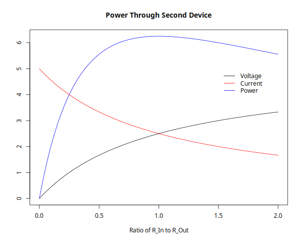 As you increase input impedance, you raise the input voltage (black line) just as in the impedance bridging case above. But a higher input impedance also means less current passing through the system (red line). The power transferred to the second device (blue line) is the product of the current and voltage. You can see that it’s maximized when the two impedances are the same.
Note that at the power transfer maximum, we’re cutting the voltage in half: 2.5 V instead of 5 V. If you care about both power and voltage transfer, you’re out of luck.
High Frequencies
It turns out that we want to match impedances at very high frequencies too. Why? Because everywhere there’s an abrupt impedance mismatch, some signal gets reflected.
At low frequencies, reflected signals don’t really matter that much. They bounce back and forth in the wire connecting the two devices so fast, getting a little bit absorbed in the wire with each trip, that they die out quickly relative to the frequency of the signal we care about. At high frequencies (say 300-500MHz and up?), the signal we care about changes on about the same time scale as the reflected signals bouncing around in the wire, and the desired signal and its reflections get confused together. We want to avoid that.
There’s a trade-off with high frequency impedance matching. Often, we really do care about the level of the voltage signal, but we’re so disturbed by the echoes that it’s worth taking the 50% loss in voltage level to make sure that there are no reflections messing the signal up. You just have to make up for this loss in voltage with some extra amplification.
So to sum up, when you want to transfer power or minimize reflections for high frequency signals, you match the input impedance of the second device to the output impedance of the first.
The Last Wrinkle: Impedance Isn’t Just Resistance
So far, we’ve been pretending that our impedance is purely resistive. But most real-world devices have a bit of capacitance or inductance to them as well, and they have frequency-dependent resistance. Capacitors have lower resistance at higher frequencies, while inductors have lower resistance at lower frequencies. If your devices have significantly capacitive or inductive input or output impedances, you’ll also have to keep in mind what frequency you’re operating at.
For voltage transfer, we’re just worried about making sure that the input impedance is high enough. Too much input capacitance at high frequencies can be a problem here.
To minimize reflections at high frequencies, you can often look up (or calculate) the output impedance at the desired frequency and add in a simple resistor to ground at the input of the second device to match it.
If you’re interested in maximum power transfer, things get messy. Capacitors and inductors don’t react instantly, and you need to match this reactance as well. This is a problem that bedevils radio transmission amplifier/antenna systems. Radio folks are very interested in getting the maximum power out to their antenna, so they have a number of tricks to make these complex impedance matches work.
But the take-away from today: try to match input impedance to your output impedance for power transfer or high frequencies, but keep the input impedance much greater than the output impedance if you’re interested in voltage signals.


I really like these in-depth articles. Any new “category” is appreciated.
I propose a “in-depth” tag for the more detailed (not news related) articles. Like the last arduino language article.
Keep them coming.
small suggestion: related bibliography at the end of article for the curiouses.
If someone want to submerge in a given subject.
That would be “any first semester textbook on linear networks”, really. For the power transmission maximum: I’d recommend taking a load resistor in series with a source impedance resistor, and a voltage source. Now, derive the power that gets converted to heat in the load resistor (hint: P=U_load*I, hence P=U_load²/R, and U_load = U_source – U_source_impedance). Then, do the good ol’ 9th grade solution (extremes of a quadratic function) or the 10th grade approach (deriving, setting to zero, solving), using R_source_impedance as free variable.
Well, having studied EE I’d personally say this article is exactly what the authors claim: An easy introduction of a topic, definitely not an in-depth coverage. In fact, I was surprised not to find at least a derivation for the trivial DC case of maximum power transfer. That’s everything, but an in-depth article! I do **not** critizise that, because the authors really never claimed this to be detailed, but you got to realize that this is barely the top of the iceberg. In fact, having had one first-semester lecture on passive linear networks, one fourth-semester (iirc) lecture on transmission line theory, and several lectures on microwave, communication technology, antenna theory etc, this seems much more like “a foggy glimpse through your gramp’s telescope at the tip of an iceberg” ;) Really, not a bad thing, things **need** to be introduced somehow, but really, not in-depth.
I like trees.
What a hyperbole. Leave grandpas alone.
Excellent article and clear summary of most common impedance situations, however it would be nice to see a reference to transmission lines which are occasionally an exception to the rule for audio. 600 Ohm balanced lines go back to the olden days of the phone system and are still used in pro audio and a similar system is also used for AC power distribution. I am actually a little foggy on the details of these systems and I suppose I could look them up but it would be nice to see another article like this which brings everything together in one useful place.
What counts as “high-frequency” depends a lot on the scale of what you’re doing. To a first approximation, a quarter wave at 10 MHz is 7.5 meters. Which means that power cords and ground wires aren’t necessarily going to act as such; some of them will act as antennas instead. (Speaking as someone who as a college student worked in a lab that wasted several months on rf leakage.)
I really liked this article…you did a great job of explaining all of the concepts. Thanks!
Please keep this sort of thing coming. This is perfect for people like me that never had the advantage of studying this stuff in college.
That! Exactly the point (imho) of this article! Keep the good stuff coming. Also, but that will take considerable amount of work, build tutorials out of this. Like: based on this, how *does* one derive the sink impedance for maximum power transfer? Kirchhoff’s law, understanding linear networks, understanding harmonic alternating current as complex currents, understanding the complex impedance of capacities and inductors… That kind of stuff.
Yeah, stuff most EEs will never use in real life anyway… shame. More like don’t cross guide the waveguide, trim semi-rigid until phase is correct, remember pick up cool end of soldering iron, if they’ve even seen a soldering iron in real life… etc… But deriving much of anything… nah.
impedance is the frequency-dependent sister of resistance
FFS get it right
resistance and reactance are siblings.
So many positive and constructive previous comments I almost forgot I was on HAD. Thanks for the reminder!
Amen!!
To prevent signal reflection, it’s not enough to match the output and input impedances – the transmission impedance must also match. Otherwise the wire in between the two devices acts as a low impedance device in a chain between two high impedance ones and the reflections appear again.
Hence why you have 50 or 75 ohm coaxial cables: http://www.allaboutcircuits.com/textbook/alternating-current/chpt-14/50-ohm-cable/
Nice link, that site is just what I needed to help my daughter understand the concepts. It even has a section that touches on the highlights on Kelvin cables.
Thanks!
Indeed, great overview, this article. And this link is quite handy for some more-in-depth info… This line is what I needed: “An older term for characteristic impedance, which I like for its descriptive value, is surge impedance. If a transient voltage (a “surge”) is applied to the end of a transmission line, the line will draw a current proportional to the surge voltage magnitude divided by the line’s surge impedance (I=E/Z).”
“Surge Impedance” is a great term that inherently explains why characteristic-impedance is a constant-value in ohms, rather than, say, some function of frequency (e.g. reactance). Wonder why they stopped calling it that…
That’s why i always use monster cables.
In RF impedance is always very important. It means good output, weak, or a very expensive failure.
Excellent essay….
I’m going to throw in with the rest and vote for a “Hackaday 101” section with really well-written essays like this for the noob, the confused and we tinkerers.
(Also a continuation of this that explains what happens to audio (& video etc.) signals when you have a really bad impedance mismatch.)
I’m with DainBramage, this is near my level and I am interested in the topic. Keep it coming.
I think these topics need their own tab to keep them together. HACK101 or some such label. The NOOBS oscilloscope pieces should be added as well. HAD could build up a true resource. Wiki style without the wiki markup language.
http://shutupandtakemymoney.com/wp-content/uploads/2014/11/heavy-breathing-cat-2.jpg
Input Impedance… Preventing one fuck-up cascading into a series of fuckuperies
Keep up those theory articles!
For >500km electric lines 50-60Hz is high frecuency! OOps.
I have a Master’s degree in electrical engineering, but have never seen this material so elegantly presented as in this article. Very good job, and please keep it coming!
I’ve built some guitar pedals and amplifiers, but never really understood impedance until now. I’ll start my Electronin engineering curriculum in a month, so stuff like this is greatly appreciated. Keep it coming!
If you have a scope that can flip between 1M Ohms and 50 Ohms, run a signal generator into it and adjust your signal with 1 M Ohms setting for a few vertical divisions, don’t touch anything but flip to 50 ohms and watch the signal… Or take a few crappy handheld meters all set to measure voltage and put them across a small signal, one by one and note the voltage on all the meters… etc.
I hated circuits when I had to study them waaay back. So now that I am trying to understand this stuff. statements like “Engineers like to think of devices like amplifiers as simply reading the voltage level at their input. But we’ve got a real amplifier, and it takes some current flowing in for it to work” are confusing to me. Why would an engineer think of an amp that way? To me it is more obvious that current will be needed in electric/electronic devices.
So, that statement just made me think….”wtf!” can someone explain the point of that statement – what does it mean? what engineer would think that??
Think of it this way… when they teach physics, one of the first things they teach is that a body in motion stays in motion… Except everyone who’s ever rolled a ball knows otherwise. So, then, weeks later after you’ve wracked your brain trying to wrap your head around something that you’ve known makes absolutely no sense since you were a child… they finally introduce the concept of friction. And you say to yourself Dagnabbit, if you’da just said that in the first place I wouldn’t’ve needed two weeks to try to understand that y’all go way out of your way to play pretend.
But, after ten+ years of learning to study that way, physics, electronics, whatnot… eventually you start thinking that way, despite its complete absurdity to the real-world… And, eventually, you learn tricks to make life easier. Instead of worrying about friction in the case of rolling a ball, there’s more important things to worry about, like the hill that it’s about to roll up. If you push that ball fast enough, and that hill’s steep enough, then friction is basically a moot-point. So, why include a teensy tiny fraction in an otherwise already complicated equation…?
So, similarly, if you’re smart about it, you *can* pretend that the input of an amplifier doesn’t require any current… *if you’re smart about it*. You can’t *neglect the fact*, but you can pretend it’s not there, if you know your circumstances allow for it. IF you *know* the circumstances allow for it. That means it *should* be *considered*, but maybe not necessarily *calculated*.
So, if you’re connecting an op-amp input directly to a battery, the amount of current going into that input is basically irrelevent… that tiny load will have basically no effect on the voltage of the battery.
And then they go ’round teaching some tricks… it’s “generally” acceptable to use the rule-of-thumb that if your load is ten times less than your source, you can neglect the load. Rephrased, think about a voltage-divider:
Vsource >—-/\/\/\/\—–> Vout >—-/\/\/\/\—–> GND
If you connect another resistor between Vout and GND, as long as that resistor is 10 times greater than Rout, you can generally neglect it.
In the case of most op-amps we’re talking >100kohms at their input… So, if you want Vout = 1/2 Vsource, you can generally neglect the op-amp’s input resistance as long as your voltage-divider’s resistances are <=10kohm.
It's just to make life easier…
and the "generally" concept, here, is something that shouldn't be taken lightly, as this article explains.
I think the problem comes with the order in which these things are taught… You go into physics and the first concept being that an object-in-motion stays in motion, then you think "I want to calculate how far my ball will roll across a carpet" and you *just can't*. Yet it makes a heck of a lot more sense to learn how far the ball will roll across a carpet *first* before learning how far up a hill it will roll before reversing direction.
Meanwhile, there're a whole generation of folks who've never connected an input voltage to an op-amp, taught the "10x rule" (but not all the details of when it's acceptable until months later) and taught that op-amps don't draw any current, then (rightly) wonder why their voltage-divider with 1Mohm resistors is giving 1/3Vsource.
If anything, I'd say folks like you are *well suited* for these realms… you don't go in unquestioningly, which is good because there's no way you could take enough classes or read enough books to learn *every* case that should be considered… you have the "real-world" intuition already, and after quite a bit of head-smacking will eventually know that they're teaching idealized cases… So when you run into something you hadn't been taught, you won't default to assuming what you'd been taught is all you need to know, you'll be capable of figuring it out. That is, if they don't teach you out of that. (And, when it comes time to take those friggin' exams, you'll be working against all your intuition to try to work in those idealized realms… it'll be harder for you… Time-crunch and tons of equations ain't enough, try that *while* actively shutting-down your intuition!)
To put it simply, the point of the statement is just to point out that many people tend to equate a device to an idealized circuit element. When they have a generator advertising a 12V output, they probably think of it as an ideal voltage source (V) and don’t care or even know the fact that the voltage will drop the moment a load starts to draw current.
When I started out as a design engineer, it was puzzling to hear people talk about the impedance of a node. But then I understood what they mean as impedance of a node is a measure of how vulnerable that node voltage is for an applied voltage source. If the node is high impedance, its voltage can easily be changed using a weak supply (one with high series impedance), whereas a low impedance node will resist that voltage change.
I wished you just start explaining what the impedance is instead of building all these circuit that requires additional ram space in my head and taking too much time saying engineers want this and want that while im still waiting for the explanation of what impedance really is you made too much data hanging in my brain and kept on adding more and more without getting to the point , this is painful , I would rather stick my eyes with pencils than continue reading
I second the comment that it is worth including the quarter wave propagation delay guideline for determining when you are likely to run into trouble telling signal from reflection if you have an impedance mismatch in the system. (I say this because it can make all the difference in the world when going from prototype on a breadboard to deploying something off the workbench because cable/trace lengths change sometimes between prototype and deployment and knowing where to expect trouble helps save time debugging (or better yet, correcting in advance)).