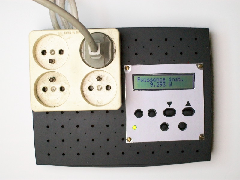
[Renaud] built a AC power meter from scratch. While commercial power meters like the Kill A Watt are available [Renaud’s] build gives an interesting insight into the methods used.
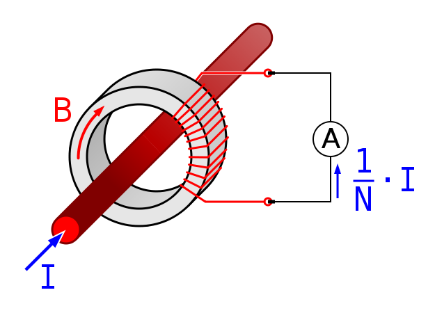 At the heart of [Renaud’s] design lie two sense transformers. The first is a typical voltage stepdown transformer. This brings the AC line voltage down to +/- 10V, which is more amenable to digital sampling. The second is a current sense transformer. In current transformers the primary is typically a single wire (the AC line in this case) passing through the middle of a ring (see the picture to the right from wikipedia). The secondary is wrapped round the ring. When the secondary coil is shorted a current in the primary wire/coil induces a current in the secondary coil.
In practice, the voltage drop across a low value resistor is used to detect the current in the secondary. Clamp meters use this principle to make non-contact current measurements. Other power meters often use hall effect sensors for current measurements. It will be interesting to see how these methods compare when [Renaud] benchmarks this build.
[Renaud] takes the voltage and current readings from these transformers and samples them with a PIC in order to calculate power. As the AC voltage is periodic [Renaud] uses a method similar to Equivalent Time Sampling (ETS) to combine waveforms from multiple cycles and increase the effective sample rate.
Great stuff [Renaud]!


Is the Phrase shift of the current transformer account for? It can cause a lot of error for non-resistive loads.
http://www.ccontrolsys.com/w/Measurement_Errors_Due_to_CT_Phase_Shift
he says he computes the power factor, so yes
The article above points out that current transformers will give an incorrect power factor reading (approximately 3% off for the specific devices in that article) unless you account for the phase shift in the CT due to parasitics in the CT. Would be interesting to see if this devices is accurate enough warrant correcting for percent scale inaccuracies, it does at least seem to do proper RMS calculations so it is likely that these last few percent could be the dominant source of error after calibrating the voltage/current readings independently
He can calculate all he wants, but garbage in garbage out. He doesn’t seem to know that it exists as there is no mentioning of it in the article. He made his own transformer i.e. one without even a datasheet.
If you have a highly non-resistive load such as a large inductor (e.g. motors) or capacitive (e.g. switch mode supply without power factor correction), the error is more than just a few percents. See that example in my previous URL. It can be double digits errors (%). 13.1% in the URL example just because the CT has a 3.3 degrees lead.
Elm-chan built one with resistive current sensing which will has less phase error.
http://elm-chan.org/works/heco/report_e.html
I was effectively not aware of this phase shift, thanks for pointing this out. I may try to measure the phase shift of my transformer to improve accuracy.
BTW the phase shift is frequency dependent, so while you can calibrate it for 50 or 60Hz, if you have significant high frequency harmonics, your result are still inaccurate. e.g. badly designed compact fluorescent light, wallwart etc as they have minimal input filter (due to cost cutting, size limitation) and usually do not have power factor correction.
“principle to make non-contract current measurements. ”
How is it different when they’re contracted out? :D
Having to resort to ETS at such a low frequency sounds like a major fail.
The sampling frequency is not that low compared to the adc speed. And even if it were, why would it be a fail ?