
Working with embedded systems usually involves writing code which will interface with hardware. This often means working on the register level. It doesn’t matter if we’re talking about a UART, an analog to digital converter, an LCD controller, or some other gizmo. Sooner or later, you’re going to have to break out the datasheets and figure out how to talk to an external device. To succeed at this you must become a master of bit manipulation.
Hardware designers don’t like wasting space, so modes, settings and other small pieces of information are often stored as packed bits. Our processors usually access things a byte (or a word) at a time, so what is the best way to handle this? Like so many other topics in software engineering, there are multiple ways to skin this cat. In C (and its derivatives) there are two major options: shift and mask, and bit fields.
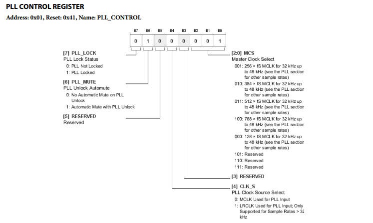
Consider this register from an Analog Devices ADAU1977, an Analog to Digital Converter (ADC). There is a lot going on here. We’ve got 6 separate data elements to deal with. Bit 7, is a read only bit, while the rest are read/write. The 3 least significant bits are handled as a single 3 bit value, used to select the master clock for the ADC.
Bit Fields
C’s native interface for describing bitwise data is bit fields. Bit fields are defined just like structures, which means they make for very easy to read code. The disadvantage to bit fields is that they are non-portable. Using bit fields means placing a lot of trust that your compiler will do what you expect it to.
In bit fields, we would describe the PLL control register as follows:
struct
{
 unsigned char clockSelect:3;
 unsigned char res2 :1;
 unsigned char clkSource :1;
 unsigned char res1 :1;
 unsigned char pllMute :1;
 unsigned char pllLock :1;
} PllControlRegister;
accessing the bit fields is just like a structure:
struct PllControlRegister myRegister;
myRegister.pllMute = 0;
Easy right? Well, the devil is in the details. Bit fields are one of the gotchas of non-portable code. Even the Linux kernel hackers have been bitten. If the project you’re working on is architecture (and compiler) specific, and you know how the compiler will work, you’re golden! However, if you have any future plans to re-use this code on a different system, you’re asking for trouble. Here’s why: The C standard doesn’t define how bit fields should be ordered. In fact, it says: “The order of allocation of bit-fields within a unit (high-order to low-order or low-order to high-order) is implementation-defined.”
 Going by that, we have no way to know if pllLock will end up in the most significant bit like we expect it to, or the least significant bit. Things get even more complicated when you throw in larger bit fields on 32 or 64 bit machines, endianness, and padding for fields that cross storage boundaries. If you’re interested in portable code, you’re better off with the other method, shift and mask, which I describe below. For now though, let’s talk about a real world case where bit fields are the better bet.
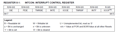
Microchip’s PIC line of processors use bit fields extensively in their own include files. For example, the INTCON (interrupt control) register on the PIC16F1829 microcontroller is defined as follows:
struct
{
   unsigned IOCIF :1;
   unsigned INTF :1;
   unsigned TMR0IF :1;
   unsigned IOCIE :1;
   unsigned INTE :1;
   unsigned TMR0IE :1;
   unsigned PEIE :1;
   unsigned GIE :1;
}INTCONbits_t;
(the actual .h file has a union, but I’ve simplified things a bit here)
Microchip can use bit fields here because they know what the compiler will do – they wrote it! INTCON is also an internal register on the PIC itself, so no worries about writing portable code. The added bonus here is that PIC has bit set and clear opcodes that can operate over all of its RAM. The compiler is smart enough to translate any bit field operation to the appropriate bsf and bcf opcodes, which operate in a single cycle.
Shift and Mask
The safer way to handle operations like this is shifting and masking. As the name implies, this uses a shift operation to build up a mask, then we use that mask with a logical operator to set or clear a specific bit. We don’t want to perform all this work on the actual hardware, so the best bet is to use a shadow of the register in RAM. First read the hardware register into RAM, then make modifications on the RAM shadow, and finally write the RAM shadow back to the hardware register. This is where the term Read-Modify-Write comes from. I know this all sounds complex, but after using it a few times, shift and mask with a shadow register becomes second nature.
Looking back at the ADC register up at the top of the article, let’s say we wanted to set pllMute, which is bit 6. The logical OR operation can be used to set a bit. In this case you need to mask all the bits you want to change with a 1.
For simplicity’s sake, assume for these examples that PllControlRegister is a memory mapped I/O location, called “pllCtlReg”.
unsigned char pllShadow;
unsigned char mask = 1;
pllShadow = pllCtlReg;     //Read the current value of pllCtlReg
//now build the mask
mask = mask << 6;          //Shift to get 0x40, or b0100 0000
pllShadow | = mask;         //Logical OR will SET the only bit 6 in our shadow
pllCtlReg = pllShadow;     //write the shadow back to the hardware
If we want to clear a bit, a logical AND is the way to go, but this time you need to mask the bits you want to change with 0s, all other bits will be set to 1.
unsigned char pllShadow;
unsigned char mask = 1;
pllShadow = pllCtlReg;      //Read the current value of pllCtlReg
//now build the mask
mask = mask << 6;           //Shift to get 0x40, or b0100 0000
mask = ~mask;               //logical NOT gives us 0xBF, or b1011 1111
pllCtrlReg &= mask;         //Logical AND will clear only bit 6 in our shadow.
pllCtlReg = pllShadow;      //write the shadow back to the hardware
If you need to toggle a bit, logical exclusive or (XOR, or the ^ operator) is the tool of choice. I’m just showing one of the most basic ways to perform shift and mask. There are plenty of ways to perform the same operations. You can use #defines, or preprocessor macros, or even functions to perform these same tasks. It all depends on what is most important for your application: memory space, or execution speed.


I don’t work in C much, but usually when I deal with bit fields, I define an Enumeration of bit flags for the masks. That makes the code a bit more readable. Is that possible in C?
Some thing like
typedef enum {PllReg = 0x40, …} RegMask;
value &= ~RegMask;
*value &= ~RegMask.PllReg;
&$*=#! to you, too!
But seriously, in these times of cheap storage and fast data transfers (at least, at the level it usually matters for embedded systems), why do we still have to put up with this bit field BS? Surely the minor improvement in transfer efficiency isn’t still worth the hassle and ugliness of decoding these things. Just spell it all out, damnit!
you can make each bit(field) a separate address, but it means a larger address decoder in the hardware and in the case of small 8bitters possibly running out of IO address space
Even with cheap storage and increased speeds, making effecient use of existing space is far smarter. Really. We have multi terabyte computers and compression utilities are still as important as ever.
External storage is still snog slow anyways. Slurp up 32/64 or however bits wide my register is and hold it in a register to get that many boolean states or slurp up the same number of bytes and keep swapping with RAM?
You can use preprocessor funk to macro pointers to a bit, making it easier yet, eg.
typedef struct {
  unsigned int bit0:1;
  unsigned int bit1:1;
  unsigned int bit2:1;
  unsigned int bit3:1;
  unsigned int bit4:1;
  unsigned int bit5:1;
  unsigned int bit6:1;
  unsigned int bit7:1;
} _io_reg;

#define REGISTER_BIT(rg,bt) ((volatile _io_reg*)&rg)->bit##bt
#define RED_LED		REGISTER_BIT(PORTD,2)
#define SWITCH			REGISTER_BIT(PIND,1)

...
if(SWITCH)
	RED_LED = 1;
else
	RED_LED = 0;
etc. It does everything for you, if you only need a single bit. Multi-bit toggling stuff is still faster to manually mask and do at once, though.
this is of mostly only useful for stuff you hit more than once like outputs, not config, since you have to configure it ahead of time, though.
And don’t forget about bit banding on ARM! Actually, I wonder how good the compiler is at optimizing for that? I wonder if someone could do some special intrinsic or bit of metaprogramming that would allow the super convenient syntax of register bit fields, but actually convert to the bitband address at compile time?
And here’s a sort of answer to my question:
http://infocenter.arm.com/help/index.jsp?topic=/com.arm.doc.faqs/15921.html
Then it would just suffice for chip manufacturers to provide a complete enough set of definitions to access all their peripherals. That would be *a lot* to write, but surely there is a higher level description of the registers and their fields somewhere at a higher level of the chip design, and the whole set of definitions could be auto-generated with a straightforward translator tool.
Still kind of crummy that it is all macros like that, rather than the reg.bit convenience of the bitfields.
I wish someone would pay me for my good ideas :'(
Take a look at Microchip’s Code Configurator plugin. It auto-generates code for almost every peripheral and GPIO. It saved me a lot of time in setting up microcontrollers so I could get to actually writing code for my application.
Maybe this is a dumb question, but why not just say something like:
pllCtrlReg |= ( 1 << 6 );
What's with saving it to a separate "pllShadow" variable then copying it back? Does that actually compile to something different?
it would be better, it would at least give the compiler a hit to use a bitset instruction if the cpu have one. The examples seems to have been written to be as confusing and verbose as possible
It should compile out to the same thing – I wrote the examples out step by step so beginners would easily be able to follow what was going on.
Depending on the compiler, pllShadow could end up being in a register, or in RAM. The advantage of a shadow is touching hardware as little as possible. Say we wanted to modify 4 bits in the PllControlRegister. With a shadow, you can read, modify all four bits, then write it back – two accesses. With direct hardware access you’d have to hit the hardware 8 times. On a bare metal microcontroller without interrupts, that’s all fine and good. However once you move up to a system with an operating system, or even just a micro with interrupts, accessing hardware becomes dangerous – which leads to discussions of atomic sections, locks, and semaphores.
From a beginner’s point of view, that was just confusing. It makes me believe I have to do it the verbose way.
As for modifying more than one bit at a time, why can’t you do something like register |= (0b101 << 3) or just writing out the whole mask you wish to write?
I respectfully disagree, Verbose == Good. Remember, code is much harder to read than it is to write. register |= (0b101 << 3) May mean absolutely nothing to an inexperienced person reading your code (or even an experienced person who is not familiar with the settings register for the ADC). So if you can be verbose and spell out what exactly you are doing, and let the compiler optimize away, that is the preferred way to go.
Only when verbose doesn’t involve a performance or safety hit. See my example below.
I agree with you. Except I do not agree that good verbosity is achieved by storing the value in a temporary variable. How about: UCSRB |= (RXEN | TXEN);
The parentheses probably aren’t needed there (not even sure!) but they do make it more clear, IMO.
Isn’t that what comments are for?
Comments are a bad way to increase readability of code. Much better is to create a function or macro with a name that explains what it does. If you see “EnableDebugPortTransmitReceive()” in the code you immediately know what is happening, without having to know anything about the hardware details.
You’re giving your compiler waaaay too much credit. In most cases when you read modify write the way you did the compiler faithfully follows your reasoning even with the heaviest optimisations set. One example is on an AVR, a simple test program which sets an output the short way vs the verbose way produced 80bytes of program code vs 138program+2memory.
The differences is that the long way compiled out to:
00000037 IN R24,0x0B In from I/O location
00000038 LDS R25,0x0100 Load direct from data space
0000003A SWAP R25 Swap nibbles
0000003B LSL R25 Logical Shift Left
0000003C ANDI R25,0xE0 Logical AND with immediate
0000003D STS 0x0100,R25 Store direct to data space
0000003F OR R24,R25 Logical OR
00000040 STS 0x0102,R24 Store direct to data space
00000042 OUT 0x0B,R24 Out to I/O location
the short form PORTD |= (1<<5) compiled out to:
00000043 SBI 0x0B,5 Set bit in I/O register
This was compiled out with -O4 (maximum optimisation) in AVR Studio.
From a safety point of view the short way is also much safer as executing a single instruction results in a guarantee that the output will only change the single bit. By comparison if after instruction 37 an interrupt occurs that then modifies the original register, a few instruction after the interrupt finishes that modification will be overwritten which is bad ™.
This may not be true across other platforms but certainly the recommended way of accessing registers according to Atmel on AVRs for efficient and safe coding is the shortened form: http://www.atmel.com/images/doc1497.pdf
Stupid me, (-O3) was the compiler flag, there’s no such thing as (-O4)
That’s what they are trying to make us believe!
The safest way to modify a register that can be manipulated by an interrupt handler is to disable the interrupt before accessing the register. :-)
If the interrupt itself can manipulate the register, say if it’s a flag bit that’s cleared by writing 0, then even the short form is dangerous, since the bit manipulation instructions could themselves do a read-modify-write. One could make many assumptions about how the hardware is implemented, but unless it’s explicitly called out in the datasheet or manual, it’s best to be paranoid.
Single instructions are atomic on AVR as far as I can tell. That is even though a SBI or CBI instruction to set and clear a single bit takes 2 clock cycles to complete, it can’t be interrupted mid execution and the bit would set and clear before the interrupt handler is called. The only case that calls out special mention in the AVR documentation that I have found is accessing 16bit registers which can’t be done in a single instruction let alone a single clock cycle on an 8bit AVR.
But you’re right not to make that assumption. This is likely platform specific, but in the case above, any code that the compiler optimises down to SBI or CBI the AVR can be considered safe, even though technically it is a read-modify-write operation.
One of the first things I learned when starting programming bare-metal C was to never use bitfields for accessing hardware registers, and that advice has served me well over the years.
Depend total on its usage, sample: if you are coding for a 8051 then its a normal practice to use bit fields as the are part of the instruction set and settings of functionality of the processor.
You’re still relying on non-portable behaviour of a specific compiler. A good compiler will be able to generate bit set/clear instructions from shifts and logical operations.
In c and Ada I create an rmw(addr, hi, lo, value) procedure. This is 32bit based so hi can be up to 31. Inside rmw is the load, maskgen&shift, replacement, and store. All my embedded reg manipulation code passes through rmw.
Ada has representation clauses that can be used to nail down what the struct (record) looks like in memory.
Indeed but Ada can optimize the read mod write to byte/half which some SoCs can’t grok. There is a thread on this up now on comp.lang.ada wrt the STM32.
It’s also legal for C compilers to access bitfields in smaller units – one more reason for why they should not be used. Some ABIs specify additional rules for volatile bitfields, but why learn bad habits that only work on specific compiler-CPU combinations when you can start writing portable code right away?
On the subject of padding in structs and bit-fields you can sometimes use the #pragma pack directive to get a known packing for greater portability. I use this if I use structs for defining packets for data transfer between different architectures like Arm and x86/x64. This will affect the read and write performance of structs, because speed wise reading ints may be faster on some systems, but for transfer of a custom packets or register definitions it definitely simplifies the encoding/decoding of data.
Between different compilers and machines with different endianness it’s still sometimes a crapshoot, but it can still be useful where your code only needs limited portability but good readability. Do test that byte order is what you expect though!
#pragma pack(push,1) //force 1 byte packing
struct some_struct {
unsigned char value1;
unsigned char value2;
};
union some_struct_union {
unsigned char array[2];
uint16 combined_value;
struct some_struct struct_value;
}
#pragma pack(pop) //Return to compiler default packing
On architectures that require strict alignment, using packed structs to represent hardware registers is a recipe for disaster.
One additional gotcha comes in the form of read to clear and set to strobe bits. This raises the possibility that the meaning and semantics of the bits in a register can differ between read accesses and write accesses. Obnoxious? Yes, but I have on many occasions encountered real devices with such register access behavior, and it makes writing a driver even more fiddley than it already is.
I never seen bitfields in real production code….and thats good so ! It’s completly unportable…
Access of hardware registers is often non-portable by nature. And bitfields in memory to save space are usually portable.
porting code is always going to be work.
making code that is more portable to start with is good. (imho)
Absolutely. Part of the genesis of this article was recalling the pain I went to porting a large system from Sparc / solaris to X86 / Linux.
That’s why I love C++ for embedded development!
I’ll have to write something up about bitfield safety on my website, but in short, you can do something like this:
template
struct Bitfield {
Bitfield operator =(const T &other);
operator T();
T raw;
};
struct MyStruct {
union {
Bitfield one;
Bitfield two;
};
};
And… All my template arguments got filtered out. GG
I always avoided learning these bit ops despite doing a fair bit of C programming. I guess I am shiftless.
You little bit-ty manipulator you…
Break it down for new comers
pllCtrlReg |= ( 1 << 6 );
=
pllCtrlReg = pllCtrlReg | ( 1 << 6 );
=
pllCtrlReg = pllCtrlReg (OR WITH) 0b0100 0000
What about an array of Boolean?
Again, the language standard says very little about the implementation of Booleans, and on many platforms they are stored as ints.
Always felt there was something funky about bitfields, so avoided ’em from the start without really knowing exactly why. Best guess was something along the lines of “what happens if you only define three bits, are they going to be in the upper or lower bits?” combined with “will it know to work with 8bits, if the device’s ‘int’ is 16?” Glad to finally have that clarified… that bitfields really *aren’t* clear, per-definition.
Hey guys, that was a really interesting read! Would you guys mind compiling together all of these firmware tutorials and posting it in a megathread or a PDF so I can refer back to any of these lessons at anytime? That would be super useful.