[GK] had some old CRTs lying around, so naturally he decided to build an old school analog scope with one of them. Lucky for us, he’s been documenting his progress. Since it was a big project to tackle, he started out with Spice modeling to work out all the right values.
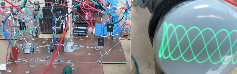
Prototyping the power supply took some custom transformer winding, but when done, the power supply did the job. Although he’s still wiring up the Z (intensity) axis, the scope is already capable of displaying signals and even text characters using a character generator he built earlier (see video below).
[GK] spends most of the time so far talking about the high voltage power supply design. For the particular tubes he had on hand he needed +200V, -400V, -550V, and 6.3VAC for the CRT heater. This is certainly not the typical Arduino-based digital scope that everyone builds at least once.
We love analog scopes for art projects, logic analyzer conversions, and gaming. Of course, if you don’t have an old CRT in your parts bin, you might consider trying a laser.


Wow. Just, wow. This is an amazing project.
This project makes me feel very humble… But, wouldn’t it have been at least a little easier to build a switching power supply using off-the-shelf parts than to wind that transformer by hand?
Eh, it IS a switching supply – haven’t you seen his site?
Since the 200V and -400V are non-isolated, he could have used a non-isolated boost supply using off the shelf inductors and switch mode power supply chips. The 550V is floating and is a bit more tricky, but it is doable if you use 1:1 inductor and voltage multipliers.
Winding transformers is easy though. Getting the cores, formers on the other hand aren’t.
Easier yes but his consideration was the amount of RF noise generated by the PSU. You don’t want too much RF interference in a measuring device!
The PSU is a linear PSU as he mentioned. It’s is not ON/OFF switched like a SMPSU. It generates a perfect sine wave into the transformer and wow what trouble he went to to make it a perfect sine wave and so you wouldn’t get ANY noise out of this! I would have used more IC’s and taken a couple of shortcuts.
The Z axis Amp has me confused. I don’t know why he didn’t use and feedback from the output transistors to the input op-amp. It may be that because the circuit is somewhat spread out that the resulting long feed back path would introduce unwanted distortion.
In any case this man’s use of constant current bias supplies and current mirrors shows that he is very experienced and knows what he is doing!
Lots of stuff has switch mode power supply in them these days. The blanket states that say switch mode supplies are bad, linear is not quite valid.
Linear Tech has an app note on slowing the slew rate of switch mode supplies to reduce the harmonics while only lowering the efficiency by a few percents. They even sell chips that does that! There is alway the option of linear post regulation and LC filtering. High voltage linear regulators exist. I got 5 of them sitting in my parts bin.
You can wire it up a resonant ZVS converter if you want a sine wave drive. I made a power supply for my VFD filament + high voltage this way as it was intended for a frequency counter.
Nice work.