Raspberry Pi Pico Oscilloscope

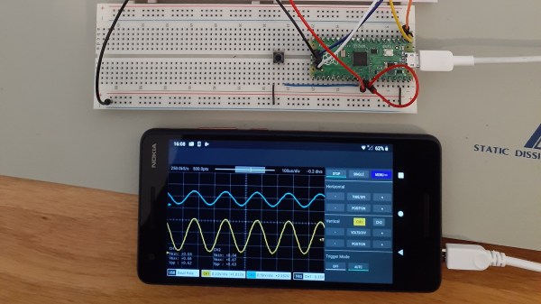
As you dive deeper into the world of electronics, a good oscilloscope quickly is an indispensable tool. However, for many use cases where you’re debugging low voltage, low speed circuits, that expensive oscilloscope is using only a fraction of its capabilities. As a minimalist alternative for these use cases [fhdm-dev] created Scoppy, a combination of firmware for the Raspberry Pi Pico and an Android app to create a functional oscilloscope.

As you would expect, the specifications are rather limited, capturing a maximum of 100 kpts at a speed of 500 kS/s shared between the two channels. Without some additional front end circuitry to protect the Pico, the input voltage is limited to 0-3.3 V. Neither the app nor the firmware is open source, and getting access to the second channel and removing ads requires a ~$3 in-app purchase. Even so, we can still think of plenty of practical uses for a ~$7 oscilloscope. If you do decide to add some front-end circuitry to change to voltage range, you can set them in the app, and switch between them by pulling certain GPIO pins high or low. The app has most of the basic oscilloscope features covered, continuous and single shot capture, adjustable trigger settings and a scalable waveform display.

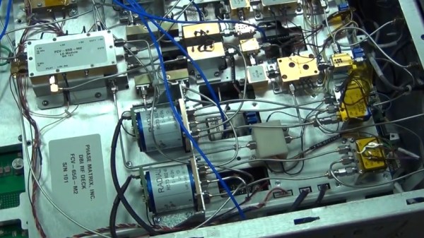
Simple, cheap oscilloscopes like these have their place, but you start to understand why the “real” ones are so expensive when you see what goes into developing a high performance oscilloscope.

Digital Oscilloscope Does Its Best Analog Impression

Do you ever find yourself yearning for the days before digital storage oscilloscopes (DSOs)? Where even the basic scopes commanded four figures, and came in a bench-dominating form factor? No, of course you don’t. The DSO is a wonder of modern technology: for a couple hundred bucks you can have capabilities that previously would have been outside the reach of hobbyists, all in a package that’s small enough to fit on even the most cramped workbenches.

Which is why the good folks of the EEVblog forums are so confused about the OWON AS101, a modern digital oscilloscope that’s designed to look and operate like the analog CRT monsters of old. Despite the 3.7 inch LCD, users are treated to the classic analog scope look, and the switches and knobs on the front should trigger a wave of nostalgia for hackers of a certain age.

But this isn’t just some “retro” look-alike, OWON is committed to delivering on that analog experience by taking away all those modern digital features we’ve become so dependant on. This single-channel scope can’t save data to USB, doesn’t have any sort of protocol decoding capabilities, and forget about automatic…well, anything. It’s even limited to 20 MHz, just like the old-school CRT scopes that you pick up for a song at any swap meet. All for the low, low, price of $150 USD from the usual importers.

In the EEVblog thread, the best idea anyone can come up with is that the OWON AS101 is designed for educational markets in developing countries, where outdated equipment is so common that there may actually be a need for faux-analog oscilloscopes to match what’s already in use. These new-manufactured “analog” trainers can be used to get students ready for a professional life of using antiquated technology. It’s hard to believe, but sometimes we can forget how fortunate many of us are to have easy access to cheap tools and equipment.

Even still, when you can get a pocket-sized 10 MHz DSO for around $50, it’s difficult to imagine how this analog-digital hybrid could possibly attract any takers at 3x times the price. If any of our readers would care to shed some light on this unusual piece of gear, we’d love to hear it.

Continue reading “Digital Oscilloscope Does Its Best Analog Impression”

Analyzing Hobby Motors With An Oscilloscope

We always like finding new excuses reasons to use our test equipment, so we couldn’t help but be intrigued by this tip from [Joe Mosfet]. He uses the ever-popular Rigol DS1054Z to demonstrate the differences between a handful of brushless motors when rotated by his handheld drill at a constant RPM. Not only is he able to identify a blown motor, but it allows him to visualize their specifications which can otherwise seem a bit mystifying.

One wire from each motor is used as the ground, and channels one and two are connected to the remaining wires. Despite the DS1054Z having four channels, [Joe] is actually only using two of them here. The third channel being displayed is a virtual channel created by a math function on the scope.

After wiring them up, each motor got put into the chuck of his drill and spun up to 1430 RPM. The resulting waveforms were captured, and [Joe] walks us through each one explaining what we’re seeing on the scope.

The bad motor is easy to identify: the phases are out of alignment and in general the output looks erratic. Between the good motors, the higher the Kv rating of the motor, the lower voltage is seen on the scope. That’s because Kv in the context of brushless motors is a measurement of how fast the motor will spin for each volt. The inverse is also true, and [Joe] explains that if he could spin his 2450Kv motor at exactly 2450 RPM, we should see one volt output.

Beyond demonstrating the practical side of Kv ratings, [Joe] also theorizes that the shape of the wave might offer a glimpse into the quality of the motor’s construction. He notes his higher end motors generate a nice clean sine wave, while his cheaper ones show distortion at the peaks. An interesting note, though he does stress he can’t confirm there’s a real-world performance impact.

Last year we featured a similar method for identifying bad brushless motors using a drill press and an oscilloscope, but we liked that [Joe] went through the trouble of testing multiple motors and explaining the differences in their output.

[via /r/multicopter]

Homebrew Analog Scope Project Log

[GK] had some old CRTs lying around, so naturally he decided to build an old school analog scope with one of them. Lucky for us, he’s been documenting his progress. Since it was a big project to tackle, he started out with Spice modeling to work out all the right values.

Prototyping the power supply took some custom transformer winding, but when done, the power supply did the job. Although he’s still wiring up the Z (intensity) axis, the scope is already capable of displaying signals and even text characters using a character generator he built earlier (see video below).

[GK] spends most of the time so far talking about the high voltage power supply design. For the particular tubes he had on hand he needed +200V, -400V, -550V, and 6.3VAC for the CRT heater. This is certainly not the typical Arduino-based digital scope that everyone builds at least once.

We love analog scopes for art projects, logic analyzer conversions, and gaming. Of course, if you don’t have an old CRT in your parts bin, you might consider trying a laser.

Continue reading “Homebrew Analog Scope Project Log”

Fast ADC Uses Old School Scope Hack For 48 MSPS

[Carlos] needed an ADC with a 50 nanosecond sample period for his laser lab, that’s 20Msps! (20 million samples a second). While in recent years, commodity ADCs reaching into the low GSPS have become available, integrated acquisition systems are still somewhat expensive. So [Carlos] decided to do what every good hacker does, and built his own solution. His project post pretty much just links to a whitepaper he wrote (PDF) so we’ll try and boil it down for you:

In order to simplify development [Carlos] borrowed a technique commonly used in the first era of digital oscilloscopes, Equivalent Sampling Time.

est

The figure to the right is from the TDS460 manual. While it may seem counter intuitive to those only familiar with modern scopes, the TDS460 achieved a 400MHz bandwidth using a 100MSPS ADC. In order to achieve this the scope acquires a single trace in multiple cycles, each time offsetting the acquisitions as shown and combining the result.

In this way, early digital scope developers could sidestep the limitations of the available ADCs to achieve a higher effective bandwidth. However there is of course one catch: the technique only works for periodic signals.

This was fine for [Carlos] who implemented a technique on a Cypress PSoC 4, which provides analog FPGA-like functionality. By offsetting the ADC trigger he has able to achieve an EST of 48MHz using a ADC sampling at 1MHz. If you want a little help getting into PSOC 4 yourself, check out the guide that [Bil Herd] made.

Neat hack [Carlos] and we hope to hear more about your laser lab in the future.

circuits of oscope

The One Million Dollar Scope Teardown

The Labmaster 10-100zi Oscilloscope is one of the fastest scopes in the world, coming in at a blistering speed of 100GHz with up to 240 Giga samples per second in real time. The scope is made by Teledyne LeCroy, and uses a frequency interleaving technology perfected by LeCroy, which allows it to provide a single 100GHz channel, or two 33GHz channels and a single 65GHz channel. The price tag? One million dollars.

[Shahriar] takes us inside the Teledyne Lecroy factory in Chestnut Ridge, NY where these scope are manufactured, and gives us the grand tour. First, an engineer describes the interleaving frequency technique that allows the lightning fast sample rates. Then they actually tear the million dollar scope down for our viewing pleasure. And if you still want more, they put it back together and run some tests to push the scope to its far reaching limits. Lastly, [Shahriar] takes us on a tour of the plant where the scopes are built.

It’s a lengthy video, so grab your favorite beverage and tuck in! It’s shocking how fast technology progresses. Just about 18 months ago [Shahriar] took us through the then reigning champion of scopes the Agilent DSA-X 96204Q which capturered 160GS/s at 62GHz.

Continue reading “The One Million Dollar Scope Teardown”

Vector Display Output On An Oscilliscope

V3zirb1

What can we say, we’re a sucker for projects featuring our logo. That being said, this one is seriously awesome. [CNLohr] has figured out how to create a vector display output on an oscilloscope… from a VGA port.

He was inspired by a game called Trace Vector, which is done in the same style as some of the old classics like Asteroids. This got [Charles] thinking, and he decided to see what it would take to make his own vector capable display. An oscilloscope is perfect for this, as it already works by controlling the position of the beam (like a vector), as opposed to standard LCDs and CRTs that use rasterizing (horizontal scanning). This means to get the oscilloscope to display a graphic, all you need to do is to vary the voltages going into the X and Y channels — well, at a high speed!

But where are you going to find such a high speed digital to analog converter? Oh yeah, your computer’s VGA port! For a few dollars [Charles] threw together a VGA adapter with a few resistors using just the red and blue outputs (source code). A bit of programming later, and he’s created his own vector display!

Stick around to see our lovely skull and cross-wrenches rotate on his oscilloscope! Oh, and for a more in depth explanation and more impressive vector video demonstration.

Continue reading “Vector Display Output On An Oscilliscope”