USB power supplies are super cheap and omnipresent. They are the Tribble of my household. But they’re not all created equal, and some of them may even be dangerous. I had to source USB power supplies for a product, and it wasn’t easy. But the upside is that I got to tear them all apart and check out their designs.
In order to be legitimate, it’s nice (but not legally required) for a power supply to have UL approval. Some retailers and offices and building managers require it, and some insurance companies may not pay claims if it turns out the damage was caused by a non-UL-approved device. UL approval is not an easy process, though, and it is time consuming and expensive. The good news is that if you are developing a low voltage DC product, you can pair it with a UL approved power supply and you’re good to go without any further testing necessary.
 If you are going for FCC approval and are having unintentional emissions testing done (which is more likely than UL as it’s a legal requirement for products that meet certain qualifications), the testing has to be done on the whole solution, so the power supply must be included in the testing, too.
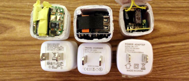
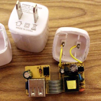
Sourcing cheap electronics in large quantities usually ends up in China, and specifically Alibaba. First, we started with a how-low-can-you-go solution. This wasn’t even a power adapter; it was a power “adapteP”, and the whole batch was mis-printed. Quality control could not be a high priority. After cutting it open, it wasn’t terrible, and it had all the necessary parts. It was surprising how much of it was through-hole, which indicates that the assembly was done mostly by people. That happens when factories are cheaper, hire inexpensive labor, don’t invest in technology, and don’t care as much about quality.
There are certain things you should look for in a power supply to determine the level of risk:
- Isolation Distance – This is how much space there is between the primary (AC) and secondary (DC 5V) sides. UL requires a few millimeters, and often you’ll see two separate PCBs. On many single-PCB solutions you’ll see a white line meander across the board to distinguish between the two. The smaller this separation, the closer your USB power is to AC line voltage, and if the gap is bridged somehow, you’re in for a world of hurt.
- Fuse – if there is a short, a lot of current starts flowing, components heat up, and things get dangerous. A thermal cut-off (TCO) fuse (also known as a resettable fuse or a PTC) is a component that breaks the circuit when it gets too hot, like a circuit chaperon. When it cools off, the TCO resets and you can plug the device back in with no harm done. Without the fuse, the supply heats up and current keeps flowing until a component fries, sometimes explosively.
- Connectors – You don’t want bare leads hanging out in space where they could move and touch something. You don’t want the USB port to be soldered only by its four pins. You don’t want the power pins to be loose.
- Decent Label – “Adaptep”? Yes, to someone who uses a different alphabet the “P” and R are very similar characters. But still. Also, fake certifications abound. Look for the difference between the CE (China Export) and the CE (Conformité Européenne) labels. And the UL Logo should have a number. So should an FCC label.
So this first adapter? Isolation distance was fine because it was two separate boards, but there was no fuse and no protective tape between components. The connectors were all secure, but the label didn’t make any promises. As for performance, output at 5.34V under my product’s load meant it was a little outside of USB spec (5.25V limit), but not dangerous. On the scope it was ringing with a peak at 5.5 V at 4 kHz.
Of course, sourcing this supply for a second batch proved tricky, and we wanted the USB plug to come out the side instead of the front so it would have a thinner profile against a wall. Additionally, we needed UL approval for a client. Our second attempt was surprisingly successful. This adapter had UL certification, with a number to look up. Note that just having a number isn’t enough; many companies will just put someone else’s number on their product and assume nobody will bother to check. So when you do look it up, and find a different manufacturer, a different enclosure, and it looks more like a refrigerator than a USB power supply, don’t be too surprised. But no, this particular one was great! The label had a company name on it, model number and specs, and certifications that could be verified. Let’s tear it open!
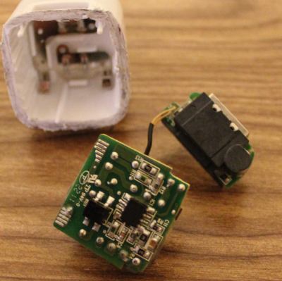 Sweet sweet silicon meat inside an ABS shell! Components wrapped in protective tape, two PCBs for isolation, and even a special injection-molded plastic piece to add additional protection. Components are labeled, and what’s this, an IC to control the oscillation instead of a feedback winding on the transformer? Fancy! It’s pretty clear that this power supply is good, and I’d trust this one.
Comparing this one to the others, there were so many noticeable little details that are important and clearly thought-out. Take, for example, the connection between the prongs and the PCB. On the previous board, it was made with wires soldered by hand. Solid, but time consuming and prone to failure or quality issues. This adapter has metal contacts that snap into the case very solidly so that the prongs cannot get loose. The connection to the PCB is via the springiness of the metal, but notice that the PCB has pads specifically designed to maximize the surface area of that connection. On the next PCB you’ll see no such effort.
Some components were covered in shrink tube, tape, or non-conductive grey adhesive. The assembly was tight with no room for components to shake loose or accidentally touch. And the output was perfect. 4.9 Volts with nary a ripple.
But this is China, and component sourcing problems are a thing, so I guess I shouldn’t have been surprised when these supplies were no longer available. In retrospect, maybe these were unsold overstock, or possibly QC rejects. That would explain why they were only slightly more expensive than the others. And so we moved on to another supplier; one that could pad-print our logo on top.
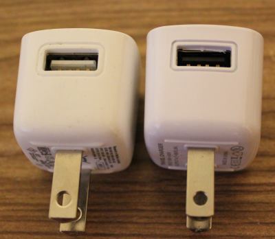 At first glance these power supplies appeared identical. But close inspection reveals slight differences in the style around the USB and the raised ridges on the underside. The label was completely different, and gone was the number next to the UL logo. There was no company name on the supply either, and the company we purchased from turned out to be a reseller and not the OEM. Also, why was the output 4.7-5V, and why did my scope say 5.5V (but surprisingly stable)?
Inside was a completely different beast. Using a single PCB, the creep distance was about a millimeter. You can see the white line meandering through the bottom of the PCB that shows the high and low sides. The USB port wasn’t soldered to the PCB except by the four signal/power pins (see the bottom side lower left and the hanging USB connection pins), and there was a capacitor with really long uncovered leads and the positive side dangerously close to the USB shell. There was almost no protective tape, no shrink tube on the leads, and no protection in case of a short.


In the end, I wouldn’t trust the two non-UL supplies with anything worth more than a few bucks, and certainly not my cell phone. I’d have really big reservations about reselling them to customers who don’t know the difference. The UL-approved one was great, but the other two are only good for powering low-current-draw devices that are not sensitive to voltage. Also, finding a reliable supplier in China is HARD.
Check out a much more thorough analysis of this and pretty much every USB power supply cube by [Ken Shirriff]. It’s surprising how little has changed in four years with these supplies, and his analysis goes into how the circuits behind these supplies work, identifying each component and its purpose.
We also covered a Sparkfun teardown of some power supplies with similar conclusions, and a Fail of the Week in which a faulty USB power adapter was the likely cause of a fire.


Interesting read, although I think that using through hole components is not a sign of cheapness as author suggests. I have personally seen an SMT diode fall off a board because the current overheated it and its solder pads. It just depends on the overall design.
I disagree, I think it is a sign of either low quality or low number of production. I don’t think there is anything wrong with through hole but nowadays nearly every company uses SMD, If someone uses through hole (for a power supply) it makes me think the company couldn’t afford a pick & place or the batch was in small enough numbers that it was not worth buying a pick & place. There may be lots of other valid reasons for not using SMD but that is what I think in general.
As pointed out bellow, SMD is not really a good option for power electronics, which is why this diode fell off.
Are you implying that computer aided construction doesn’t exist for through-hole design? Man have I got news for you.
It does but I should have said I was thinking about mobile chargers and the likes, Using through hole for something designed to be small seems stupid.
Open up even a brand new computer PSU. Most of the logic and control may be surface mount, but the major components dealing with the power handling (diodes, mosfets, capacitors) will all be very chunky through hole components. SMD is nice, but it just lacks the power handling capability of through hole, and depending on the component needed, they’re simply too small. Big value capacitors, high wattage resistors, high amp rated mosfets, big diode packs and more are all in power supplies and other electronics that deal with power, and they simply wouldn’t work as SMD devices.
I agree, I should have mentioned I had usb, mobile phone charger in my head. through hole is a must for some high voltage stuff. You are totally right.
Hmm…
Go compute the life expectancy of an aluminium electrolytic capacitor. Contributing factors? The physical size of the part. A large value, high voltage capacitor isn’t practical for surface mount without very large pads.
X and Y rated capacitors at 305VAC seem way more common in through hole. Not sure if there are even any options in SMT.
It’s a crapshoot buying from China. You never know what you’ll get.
There’s absolutely nothing wrong with using through hole components (except the final product will be larger than the same design using SMD parts).
“It’s a crapshoot buying from China. You never know what you’ll get.”
Note to self: Never buy a box of chocolates in/from China!
B^)
If it’s milk chocolate it could be laced with melamine
It’s not chocolate, it’s “chocoltae”
On the contrary, you always know what you will get: screwed
You are also screwed if you dont use CHina.
Race to the bottom has been completed: multinational corporations won. We have hit bottom.
Actually no, you just have to have a little experience to detect bullshit, sometimes even risk when stakes are not high and you’re on a good way to save a bunch of money you would spend buying from “reliable dealers”. But generally avoid power adapters, chargers and other mains powered devices with extremely low prices, they are almost always fire and shock hazard.
Even reliable dealers sell counterfeit parts sometimes.
What do you do when the boards come back from the assembler, and the FTDI chip isa convincing fake, and the driver just started mocking you?
Use your bullshit detector.
“Avionics, military and space are plagued by counterfeit parts. They must have no experience to detect bullshit.”
Sarcasm detected! Those industries also have a high markup that attracts the bullshit, and where the markup is really high, encourages high-end bullshit. Keeping up with the fakes is cat and mouse at my level, but with avionics fakes it’s like lion and, um, super-mouse.
@Elliot Williams
I’m imagining a manufacturer that makes a great product and sells it for a great price, but a random package out of every thousand actually contains a wolverine with a headache.
Sadly, it’s a crapshoot buying from anywhere these days. But if you buy from the US / EU, at least you’ll have paid for a good item, even if it’s still just cheap crap with a big margin.
The difference is, that if you buy from an authorized distributor, if the parts turn out to be counterfeits, you can get your money back (though you’re still on the hook for the rework of the bad boards).
I think the only way to avoid getting screwed in China is to be there, and have partners you trust (difficult, but perhaps possible) or to be Apple (slightly more difficult) and partner with a Chinese company who will guarantee their work and that of their suppliers for you.
In general, our line only avoids through hole because the labour cost is higher for large component filling. Thus, only places with subsidized (recall China is communist) or low labour cost (India/Philippines) will design products using the older assembly standards. Note, many Pick-and-Place machines can take a roll of through hole parts on tape.
However, one will find through-hole is sometimes the only economical form factor available when it comes to power electronics (more common if drawing >5A on output). A surface mount inductor will usually need glued down, power rating of SMT form factors is almost always lower, and some isolation components that need the air-gap to form a proper barrier will not be found in SOIC (note the DIL6 SMD versions of some chips). Failure modes for a through hole board tends to cook parts, but is less likely to pop off components.
Most high end equipment uses isolated power modules, and these use a multi-layer PCB as the windings in split inductor sandwich. However, most consumers like the article’s author will never pay for such an expensive product (around $30 just for the power section).
“Fast, Cheap, or Good…. Choose any two…”
Through hole parts also have another advantage which is often used, especially in things like the Power Supply mentioned in comments above.
The greater mass of metal allows for better thermal sinking, better heat dissipation, and so on. Surely much of this advantage has been narrowed with modern SMD parts, but for things like FETs in a power supply, it is obviously still a potential advantage.
“The greater mass of metal allows for better thermal sinking, better heat dissipation, and so on. ”
If the through-hole part is attached to a heatsink, sure. But a through-hole part that’s *not* heatsunk will have pretty impressively terrible thermal performance compared to an SMD device of comparable area on the PCB, because the pins are typically just wire-bonded to the die, giving terrible thermal performance.
Thank you. Nice to see this was the first comment.
Something else to pay attention to lest it bite you in the back end when you’re not looking.
You forgot to check and mention the power transformer inside. I’ve seen transformers using ordinary office type tape as insulation between primary and secondary windings. Will melt easily and probably won’t provide enough insulation even from the start…
Yup, and you won’t find out until the thing fails. The components may LOOK good, but who really knows?
UL does, for the US.
That’s why a transformer’s individual components make up a UL listed insulation system complete with a temperature class rating. Next those compatible components (wire, tape, varnish, bobbin, etc) are constructed to create a transformer that will meet a different, specific UL standard, likely to be a Class 2 transformer, UL-5085. UL-5085 will set the requirements for dielectric withstand voltage between primary and secondary, primary and the core. Often this is 1000VAC + (2 * input VAC), but it is determined by the standard.
If you had the UL “E” number for transformer, you could look up its insulation class, etc.
Finally the product itself, being intended for use with telecom equipment is UL Listed to UL-60950. That standard is harmonized with EN-60950 for those who want to make a product compatible with other markets.
That’s the way it’s SUPPOSED to work (and the way it works in Western countries).
Try to find a manufacturer’s name or part number on those Chinese components. Without those, you can’t check the UL database. If there’s no marking on the part, I would assume it’s non-compliant. Any reputable manufacturer would mark their parts and be proud that they are UL compliant.
CSB: On a recent project, I attempted to design a high voltage switching supply transformer to meet IEC 60601-1 and get it approved by UL. Between the gaps in the 60601-1 spec (it’s specific enough for line voltage, but depart from that and it’s not anywhere near as clear), and UL being unhelpful in suggesting how we might meet it, we ultimately gave up and managed to find another approach. I gained a real appreciation for the challenges of transformer design.
60601 is medical, right?
A lot of these products have such a significant mark-up that unless you are in the business of selling medical grade power supplies, you are better off just buying a pre-approved one.
UL is not actually allowed to tell you how to pass the test. If they did, and you used their suggestion, and in the end it did not work and someone was hurt, UL could be liable (in the US.)
Separately, unless you are a transformer supplier, you are better off contacting a transformer supplier, giving your required specifications including insulation class, dielectric breakdown voltage between primary to secondary, primary to core and secondary to core, etc., and have them design a custom one for you.
This! The insulation distance is one important thing but this is quite easy to check. The problem is the transformer that is much more difficult to check. In the last HaD-Links there was a link to a teardown of some crap transformer that connected mains to secondary output on a USB power supply: http://www.youtube.com/watch?v=3Hdn0MuCK_0
There are devices for testing insulation, like UT511.
I have an usb adapter where one can read “5V 2A” and just a bit further “5W”… It seems that Ohm Laws don’t apply at some China places :-)
I’ve seen devices like that. When you set your load for 0.5A voltage stays at about 5V, when you increase load to 2A voltage drops to (unusable) 2.5V. So you indeed have 5V, 2A and 5W, but not in the same time :)
After a cheap USB power supply went bang (a capacitor popped when it’s regulation failed and started to output 24v) I’ve shyed away from buying any more cheap USB supplies off of Ebay. The one that went bang had reasonable isolation but of course would have killed any devices connected to it. I’ve also opened up a few other ones that with things that I ordered. A few had only a mm or so isolation distance and somewhat dodgy soldering. Others looked reasonable in terms of soldering and isolation. Of course that’s no guarantee that the ones that looked safe are actually safe; I would also have to tear apart the transformer to see how well the windings were isolated.
I’ve mentioned previously the batch of Chinese outlet strips we bought about 2 decades ago that had a UL on the label.
The Line and Neutral wires were swapped where the line cord was soldered to the power rails.
I’ll bet you a donut that the solder joints were not mechanically secure, just wires laid against copper strips and tack-soldered.
The article says “So this first adapter? Isolation distance was fine because it was two separate boards”, but the second board – the one with the USB connector – has an optocoupler. This makes me think that both boards have an high voltage part.
The part number on that component is PC817C. The multimeter said it was 8V AC. So two of the four lines coming into the second board are AC, but not high voltage. It’s impossible to have complete separation on two boards, as the optocoupler has to be on one of the two, but with the optocoupler on the second board, it’s only low voltage AC on the second board, so isolation distance is still important but doesn’t need to be as high because the arc distance is lower. Thank you for pointing it out and making me dig deep into it.
It is actually possible, I’ve seem images of PSUs with the optocouplers pins bent straight, one side going into the HV PCB and the other side into the LV PCB. Not that that’s a very good solution, mechanically, but it is possible.
You need to realize that the optocoupler is the primary feedback means in any UC3842 or similar design.
It’s actually unusual and new to not have the optocoupler feedback.
Look at most of the Topswitch parts for flyback converters. Most use an opto in the feedback loop. The feedback loop straddles high and low voltage sections.
It’s not just the voltage across the optocoupler in normal operation that’s the problem, it’s the fact that the mains side is going to be somehow referenced to the mains line voltage so the voltage between it and something grounded (e.g. you) is potentially the full mains voltage. (Also, be sure to test the voltage between it and ground with the plug both ways around.)
You can have something that is “low voltage” but still not galvanically isolated from the mains line. (Like transformerless power supplies, for example.)
A decent SMPS has a “line side” and a “cold side” which is usually spanned by only a couple of components – the transformer and the feedback optocoupler. The number of components that “jump” should be kept to a minimum, because those components have to specified for HV galvanic isolation.
It’s the hipot insulation rating of those components that matters, and the creepage distance under them.
If the “firewall” is a simple, straight, short line, then it’s easy to look at the board and check if the creepage distance is safe. (Assuming that the optocoupler, transformer etc are themselves known to be constructed with sufficiently strong galvanic isolation!)
You can see this for yourself if you take apart a well made SMPS, like say a computer power supply.
But if that galvanic isolation barrier between the hot side and the cold side is meandering around and it’s being transferred across multiple PCBs and multicore ribbon cables and stuff, then it’s a whole lot trickier to check if it’s acceptably safe.
That was interesting! Would really like to see something similar done for USB power banks, lithium cells, “dual 1A/2A outputs”, and rated capacity tests.
Excellent link for such stuff : http://lygte-info.dk/
That guy tests bunch of powerbanks, adapters, batteries. Usually adapters are torn down for quality inspection and also tested for high voltage leakage. Batteries and powerbanks are tested for their capacity and current capabilities.
Thanks, I just wanted to point to this site. HE is the GOD of power supply testing …
Errr, I don’t mind minor typos, but … It’s supposed to be “Conformité Européenne”, not “Communite Europeanne”.
Whoops. You are correct. I fixed it. Thank you.
I like it better the way it was before. Change it back.
you know why doesnt china just commit theft of service and rig the electric meters to get free electric instead of building death traps.
if i was the utility i would just give them free electric and charge the residential customers more to make up for the free electric to the factories
Asinine gibberish.
think about it would you rather give the factories free electric and bilk your residental customers or see chinese factories put out dangerous and deadly even poisonous products?
What I want is a USB brick that will detect the special needs of Samsung, iDevice etc. then pump out the maximum amount of power the device can take, without costing the ripoff prices Samsung and Apple want for their special chargers.
Do you really want questionable chinese engineering to “determine” if it should be pumping out 9, 12, 15V on its poor little USB port?
Do we really want predatory, asymmetric trade agreements (ie corporatist globalization via debasing western norms) encouraging the trash products make it here in the first place?
So many questions for the modern citizen… sigh.
Amps, not volts. Short the data lines and many USB devices will pull up to one amp. But one amp isn’t enough to keep a Galaxy Tab or iPad charged while it’s being used.
Traditionally true, yes. But I really do mean volts not amps. The fast charge “tech” actually pushes out more volts (thus more watts)
In other words,
Something that his this:
UCS1003-1
http://ww1.microchip.com/downloads/en/DeviceDoc/20005346B.pdf
Now I need to find a charger that uses one of those chips.
I’ve been looking for a grounded USB charger (ie plug with 3 prongs) but haven’t found any. Does anybody make something like this?
Why? Grounded electronics cause quite a lot of issues, especially when connecting to other grounded electronics.
Most large appliances (eg Desktop computers) are grounded. I need a ground referenced antenna powered by USB. Odd application I know but… its Hackaday!
https://en.wikipedia.org/wiki/Counterpoise_(ground_system)
The shield of a USB connector is grounded to the dead metal, earth ground of the host that you plug it into. It is connected via a ferrite (high frequency impedance) to the USB DC GND.
So if you plug it into a PC, and the PC is powered by a cord with an earth connection, that USB device has an earth ground reference.
I’ve never seen a USB charger (or any power supply for that matter) explode but those are some engineering disasters. Something tells me these were made by some of the same people to whom we outsource our programming.
How do I find one that is guaranteed to explode?
Be a leading critic of government snooping.
They all are, sooner or later.
There’s a fun DEFCON talk on the subject. She hit power switches (?) with HF, turning them on and off fast enough that they’d explode. If we didn’t cover that, we should!
Big Clive (may he live, prosper and be healthy!) actually made a song about this: “The cheap shitty pink USB charger from China song”.
https://www.youtube.com/watch?v=ioAq7PI1Uwg
All the worlds supercars sure got better when they started being mass produced by machines instead of filthy human hands.
Something tells me there are more factors at play with quality here than a lack of automation….
Anyone ever tested UGREEN stuff? Their products look good and keep cool during delivery of 2.1A.
Of cause it is China too, so I was wondering… example: http://www.aliexpress.com/item/Ugreen-5V-4A-3-Ports-USB-Charger-station-dock-stand-Cargador-adapter-EU-plug-for-iPhone/32418801216.html
Some original cuppertino products are funny too.
Somebody here in the comments has mentioned Big Clive already, he has also torn down a charger from IKEA: https://www.youtube.com/watch?v=uRe9w5PKmsE
They are quite cheap and supposedly safe. I guess IKEA can’t risk their name.
how do they prove it is non ul approved?
most filres are so bad it totally makes the source unrecognizable i.e. they can only tell it was a power supply they cant get any markings from the power supply unless they are lucky and the power supply spits a couple sparks and lights some paper nearby that limitedly burns something else and the fire goes out or gets put out in time so the power supply is melted and not burned to a cinder.
other things the ul label can be faked
I am not an insurance investigator, but I play one on the Internet. B^)
Seriously, not every fire is total destruction, some fires burn themselves out without collateral damage.
(For example: A friend and I were eating supper once and the power cord of a nearby toaster oven started sparking and smoking and burned to plug and then extinguished- I’d taken an educated guess to say that the fire was caused by a defective toaster oven cord B^) )
Other fires are put out leaving much of the structure intact (even if a “Total Loss”) allowing investigators a way to “walk backwards” the path the fire took and find a likely source.
Just to point out that there is no such thing as a CE (as in “China Export”) marking, only fake CE (as in “Conformite Europeenne”) markings. See Chinese Export…? for some backfground.
If you want to power something permanently, don’t use a phone charger or anything with a USB in it. They are all made for low duty cycle(charging your phone for a couple of hours a day).
I would be happy if I just could find one that doesnt spew RF hash all over the HF bands.
At home, I can manage by only charging at night, but the USB chargers for the car is equally bad, and then I need to charge simultanious with using the shortwave radio…
I guess charging from a powerbank would be one solution.
At home I made myself a Transformer+Linear-Regulator solution for exactly that reason… …a Linear Regulator should also be quite comfortable with the 11-15 Volts of a Car.
Take one thats rated for “Up to 30V” and you should be okay with a passive heatsink…
Having dealt with UL for almost 30 years, myself and many engineers call them the electrical mafia with snickers all around, but they do serve a purpose. Having sat on the board of several UL standard committees I can sincerely tell you, they are not out to get you, your product designs or anything like that.
Expensive? You bet. UL8750 which covers LED lights, will run 4-8 grand. Things that can kill someone? Like a garage door opener? 40-80k. A UL listed fire door? Upwards of 100k. But there are reasons.
Electrical spacings have to be followed. Creepage and clearance have to be obeyed.
You will not find a single big box retailer that lets products sold that don’t go through a NRTL. Won’t happen. Doesn’t have to be UL, it can be CSA, ETL, or anybody else, but it has to be NRTL certified.
What does CE buy you? Nothing. Anyone can be CE. Not everyone can be NRTL certified. Forget UL, or any other NRTL, as California goes, so does the nation. Like it or not a “wall wart” has to be at the last time I checked, 85-90% efficient because California dictated it, Arizona was the next to collapse and then so did the nation.
Think about it. A big hunk of humming iron is a lovely wall wart and not really efficient. Hence we got to where we are today. The Chinese don’t give a crap, forget about something that you plug into the AC mains. I have bought cheap chinese cr@p off ebay in the forms of batteries that don’t last a year.
As long as the Chinese have this sell it cheap and replace it every year mentality they will be where the Japanese in the 50’s were. The thing is looking at where it was made, and how it was made. There are plenty of great things coming out of China, but only when quality is required.
At the company I work at now, we buy a red 3528 led for 7 tenths of a penny 0.007. We use it for an indicator light. An LED for the price of a resistor or close? How? Well we bake ’em to a Mil spec that is ‘obsolete’ and throw the ones that fail due to die bond fractures in the garbage. We usually get a 50% fall out rate.
The problem is not with anything other than what we are willing to accept. I have a refrigerator from 3 generations ago that still runs fine. But it has one of the weird handle thingies that would allow a kid to lock another kid in it. It has to be (GASP!) defrosted twice a year. But it freezes ice cream like nothing you would see. Arctic Cold. It isn’t nice to look at, it isn’t stainless steel, it won’t ever be connected to the internet (it is, via an arduino…lol). However it works.
Take your new “fridge”. Sidenote, at one time there was this company called GM Refrigerator and well… anyhow. When you go to buy ANY appliance, type in the model # and the word sucks. Caveat Emptor on all that.
I have worked on designs for many appliance companies, and just like a basic garage door opener is around 38 bucks landed, a $2400 refrigerator is around $400 bucks.
I have a stove and dual oven that was built by American Motors’ Nash Kelvinator division. Still works perfectly. Stuff used to be built to last FOREVER. My grandparents had an Amana freezer that was the complete opposite of a TARDIS. The walls and vaultlike door were about a foot thick. For over 50 years it ran without fail, never needed any repair. Unplugged it and cleaned it out after my grandmother died. Probably still in the basement of the old house because one of the two stairways was too narrow to get it through and the other one (which it had been taken down through) had been narrowed by building finished walls against the old brick. Built. To. Last. Potentially nukeable…
Just a note about fuses and such. It’s not a good idea to use the terms TCO and PTC interchangeably. First, PTC, (Positive Temperature Coefficient), refers to a temperature-sensitive resistor that may or may not be the type used for over-current protection. So even the term PTC is context-sensitive, and doesn’t always refer to a self-resetting fuse. Second, a TCO, (Thermal Cut-Off), refers to a protection device that opens, (one time only or self-resetting), in response to too high a TEMPERATURE, not too high a CURRENT. The one-time types are found in, for example, rechargeable battery packs, to open the circuit if the pack gets too hot. The self-resetting types are effectively miniature thermostats, and can be found on some motors, such as in exercise treadmills. Both types may be found in various household appliances. But the important point is that a TCO opens when exposed to too much heat, while a fuse opens when there’s too much current flowing through it. A PTC over-current protection device CAN open when its environment gets too hot. Also, a high ambient temperature can cause a PTC to trip at a lower current than it’s designed for – this is known as ‘nuisance tripping’. So a TCO opens the circuit in response to overheating. A fuse opens in response to over-current. A PTC self-resetting fuse is *designed* to open *primarily* as a result of self-heating caused by too much current, but is also somewhat sensitive to ambient temperature.
Most interesting. You’re write-up has given me insight into what to look for. I’ve always been suspect of some of the cheap wall warts.
I recently tested and tore down a bunch of 12V Chinese adapters. Scary stuff.
http://www.edn.com/electronics-blogs/benchtalk/4441809/My-kingdom-for-a-12V-adapter