It’s the easiest thing in the world — simple, straightforward serial data. It’s the fallback communication protocol for nearly every embedded system out there, and so it’s one that you really want to work when the chips are down. And yet! When you need it most, you may discover that even asynchronous serial can cost you a few hours of debugging time and add a few gray hairs to your scalp.
In this article, I’m going to cover most (all?) of the things that can go wrong with asynchronous serial protocols, and how to diagnose and debug this most useful of data transfer methods. The goal is to make you aware enough of what can go wrong that when it does, you’ll troubleshoot it systematically in a few minutes instead of wasting a few hours.
The Groundwork
 Imagine that you’ve got eight bits of data that you want to send me, electronically. If we have eight wires (plus ground) between us, you can simply flip your eight switches and put high or low voltages on each wire. If I’m on the other end with some LEDs, I’ll just read off which ones light up and we’re done. But eight wires is a lot of copper. So instead you decide to send one bit at a time, using just one wire (plus ground). That’s the essence of serial communication — bits are sent in series by varying the voltage on a wire precisely over time.
Sounds easy, but now we have some choices to make. How fast do you send each bit? Does a lit-up LED represent a 1 or a 0? How will I know when your message starts or stops? And finally, if we’re both going to send data to each other, we’ll need two wires. How do we know which one I’m sending on and which one you’re sending on? Each of these choices is a place to get things wrong, and for bugs to creep in.
RX/TX
That last point, which wires transmit data in which direction, is surprisingly a common source of confusion, so it’s a good place to start debugging.
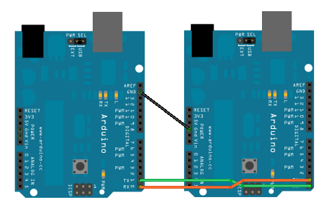
“RX” and “TX” stand for “receive” and “transmit” respectively. Most serial communications systems will have one of each. Often setup goes something like this: you’ll find yourself connecting “GND” on one device up to “GND” of the other. Maybe they’ll also share a power rail, so you’ll connect “VCC” of one to “VCC” on the other. And then, on a roll, you’ll connect “RX” on one device up to “RX” on the other.
And that’s mistake number one. Both devices are expecting to receive data on their “RX” line, so they both just sit there waiting while the two “TX” lines will end up talking over each other. No, the “right” way to do it is to connect the “RX” port of one device up to the “TX” port of the other and vice-versa. That’s just logical, right? To help remind you of this, sometimes the “TX” will be labelled “TXD” where the “D” stands for “device” and that’s supposed to remind you that you’re looking at things from this device’s perspective.
Whatever you call it, connecting a port called “TX” to a port called “RX” causes trouble in modern CAD programs, where you name the network rather than the individual ports. What do you call a wire that connects both devices’ “GND” pins? “GND” is a good name. What do you call the wire that connects “TX” to “RX”? How about the one that connects “RX” to “TX”? Confusion reigns.
(Note that SPI, which has its own issues that we’ll get to next time, calls these lines “master in, slave out” and “master out, slave in”. The line names are consistent, and if you know which device you’re looking at, you know instantly which direction the data is flowing. That’s much better.)
So the first debugging question to ask yourself is whether or not you’ve properly crossed the signal lines. And even if you have, try swapping them anyway because even if you’re not confused, you can’t be sure that the engineer upstream of you wasn’t. (We’ve seen it happen.)
Baud Rate
We’ve got the wiring straight, so how about the speed at which you’re sending (and receiving) data? This matters, because if you see a high voltage on your wire for a while, you need to know how many bits that “while” was supposed to represent. If I send you four zeros, you’ll see a constant voltage for twice as long as if I sent you two, but we have to agree on a timebase so that you can be certain I didn’t just send two zeros, or eight.
The number of bit signals sent per second is called the baud rate, and it’s something that we just have to agree on. This means that both the sender and receiver have to have fairly accurate clocks onboard so that they can keep the same time.
Be on the lookout for baud rates like 2400, 9600, 38400, and 115200. If you don’t know the baud rate of your target device, it doesn’t hurt to try them all out.
Autobauding
There is a clever trick that you or your device can play if you don’t know the baud rate ahead of time. If you receive a few bytes of data, you can keep track of the length of time that the voltage is constant on the line, and find the lowest common denominator. For instance if you see a high voltage for 208 μs, and then a low for 104 μs, and finally a high for 312 μs, it’s a good bet that a bit period is 104 μs long, and that corresponds to 9600 baud. If it’s more like 8 μs, that’s 115,200 baud. Solved.


Voltage Levels
You’ve got the “RX” and “TX” lines straight, and you’ve figured out the baud rate, so you’re well on your way to receiving and transmitting data. The question now becomes how to interpret it. Put another way, is a high voltage a 1 or is a high voltage a 0?
RS-232 vs TTL Voltages
You wouldn’t think this would be confusing, but alas, history conspires against us. RS-232, the most popular serial standard of old, used positive and negative voltages (from 3 V to 15 V and from -3 V to -15 V) to signal 0 and 1 respectively. Yes, that’s right. A 1 is sent with a negative voltage, and the higher voltage corresponds to a 0.
Cut to the present, where single-sided signalling is more common. Nowadays, the higher voltage (3.3 or 5 V) is taken to be a 1, and the low voltage (0 V) is taken as a zero. So the answer to the question of how to interpret the voltages as numbers is: it depends. Modern, but still RS-232-style, signaling will use 0 V and 5 V as 1 and 0, while TTL serial will do just the opposite.


The good news is that it’s possible to tell these two cases apart with an LED (or a multimeter if you’re fancy). Both RS-232 and TTL systems start off with the “TX” port of a device sending a 1 level as default. If the “TX” line idles high, you’re looking at a TTL system. If it idles low, it’s more than likely using the RS-232 polarity.
Inverter Circuit
 If you’ve got an FTDI USB-to-serial cable, or one of the clone devices like the CP2102 or the … , you’re 100% in TTL-serial-land. Good news. If you need to interface with another device that uses RS-232 levels, however, you’ve got a little work to do.
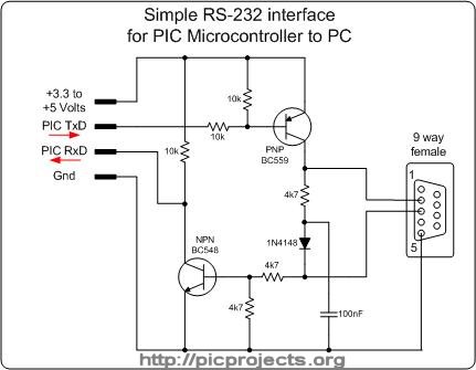
Here is an RS-232-to-TTL converter circuit that works for modest baud rates, and even takes care of the voltage-level shifting for you. So you can connect your 3.3 V sensitive ESP8266 circuits to an old -15 V to 15 V line printer and all will work just fine. This is one for your tool-belt. It’s not strictly compliant, because it doesn’t swing to -12V (or whatever), but it gets the polarity right and will work with most devices.
If you need something to interface with ancient RS-232 equipment, you can pick up a chip (MAX-232 or equivalent) that creates the higher voltages for you. Indeed, if you crack open an RS-232 converter, you’ll sometimes see a USB-TTL serial chip paired with a MAX-232. (The cheap ones simply invert the signal and are no better than the two-transistor circuit above. You’ve been warned.)
Start Bits, Stop Bits, Parity, and Endianness
You can’t just send voltages down the wire. You have to know when the signal starts and stops, and what data to look for. Collectively, this is called framing. Most serial systems will use the same “8N1” frames, but when they don’t, it’s worth knowing about. These three characters correspond to the number of bits sent at once, the parity bit, and the number of stop bits respectively. Let’s take that apart.
The number of bits of data sent per packet is self-explanatory, and most serial protocols send data one byte at a time, so this isn’t usually a problem. But on really old gear, you’ll sometimes see seven bits — ASCII only uses seven bits after all. Anyway, the number of bits per packet is the “8” in “8N1”.
Now let’s think about the “start” and “stop” bits. Because the sending device’s “TX” port (and the receiver’s “RX”) idle high (for TTL), you can’t start off your data transmission with a 1 — how would you tell if it got sent? So a start bit, always low, begins the packet of data.
If you send one byte, it ends with the line high for a long time, and it’s pretty easy to tell where it ends. If you send two bytes, and the second starts with a low start bit, you need to send at least one high stop bit at the end of the first packet. (When you send one byte, the stop bit blends in to the background high state of the TX line.) If you’re keeping count, that’s a minimum of ten signals to send eight bits: one start bit and at least one stop bit. But some systems send two stop bits, so again you have to specify. The number of stop bits is the “1” in “8N1”.
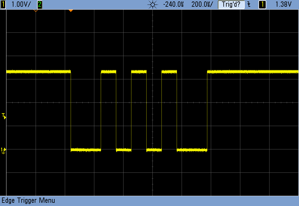
Here is the message “*\n” — Star and Line feed (ASCII 10) — being sent with one and two stop bits respectively. In binary, that’s 00101010 00001010. The stop bits (one and two respectively) show up between these two bytes, and there’s a single start bit before each as well. See if you can puzzle that out.
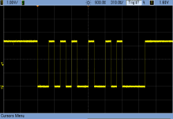
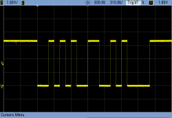
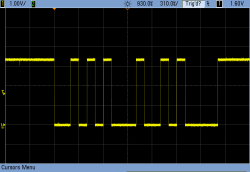
And this brings us to the “parity bit” in the middle, that is high or low depending on whether the number of ones in the data are even or odd. And the choice to encode even as a 1 or odd as a 1 is arbitrary. To take advantage of the parity bit as an error-detection mechanism, you need to know which is which, so it’s specified as “N” for no parity, or “E” or “O” for even- and odd-parity respectively. When there is a parity bit, it’s added after the data, just before the stop bit(s). The parity bit makes the number of 1s in the byte even or odd, respectively, which is the error detection scheme. If you’re using even parity and you see three 1s, including the parity bit, you know there was a transmission error.
There’s one final confusion that you’ll fortunately almost never see: the issue of endianness. The serial numeric data could be sent either with the least-significant bit coming first in time, or the most-significant. The good news is that TTL and RS-232 serial data is almost always least-significant bit first (or “little-endian”) but some other serial protocols, like the Internet protocols, send their serial data big-end first. The bad news is that scopes display data left-right as it comes in, and we write numbers most-significant-bit first, so you’ll have to reverse the bit patterns in your head when reading the scope shots. (Those four zeros in the line feed character should help orient you.)
The Protocol Layer: Line Endings
By now, you’ve got the signals all straightened out. You’d think that there’s nothing more that could go wrong. But wait! Because serial comms have evolved over time, there are two (maybe three) possible ways to signal the end of a line of data. The line-endings issue is familiar if you’ve copied text files across Unix, Windows, and older MacOS machines. Each one (naturally) uses a different standard. Confusion among these three traditions has also invaded the world of embedded devices. If the receiving program is waiting for one of these, and you’re sending the other, it won’t know when you’re done and will just sit there.
The short version is that you might need to send a Line feed (LF, ASCII 10) or a Carriage return (CR, ASCII 13) or both (CR+LF) before the other endpoint responds. Most terminal programs will let you set this on the fly, both for sending and receiving, so it’s no big deal to troubleshoot by hand. But if you’re already unsure of what your microcontroller code is doing, and you can’t see any of this to tweak, it might not occur to you that you’ve got a line-ending issue. And of course nothing stops anyone from using their own specific end-of-line character in their protocol. Sigh.
Summary
This concludes our guide to troubleshooting serial lines, and I’ve covered pretty much all of the possible variables: getting the lines right, selecting the proper baud rate, figuring out the line polarity (TTL- or RS-232-style), data length, stop bits, parity, and the line ending. That’s a lot that can go wrong all at once if you’re just trying to get some data out of an opaque microcontroller system. Knowing all of the possible factors, however, gives you a foothold — a checklist that you can use to make sure that everything is working the way you think it should be.
Most of the time, it’s not so bad. You’re going to be running into 8N1 at one of the standard baud rates. Make sure your wires are crossed, and test the voltages on the transmit lines to establish the parity. Then, you can mess around with different baud rates. If this doesn’t save you, try the line endings. And if you’re still stuck, break out the ‘scope and dig into the signals.
Hope this helps, and happy debugging! Next, we’ll take on SPI.


I use long glorious names for my UARTS to avoid any ambiguity. Eg, UART_MCU_TO_LOADCELL. It cuts down the amount of blue-wire on my boards.
Good tip! Harder to type, but much harder to get wrong. :)
I found ‘D2H’ and ‘H2D’ (device to host/host to device) work well for me in place of tx/rx.
Don’t go overboard with overly long names. When the names get too long, it actually makes it harder to read in all caps. Good until you get hit with a few typos on a large design spanning several pages. Some old CAD software only takes the first n characters for the net names.
in this case i would go serialUC2LC
Some good tips there. I look forward to the SPI article.
You can use most input captures (ICP) as the RXD pin and it makes auto-bauding and even auto-polarity far easier. I wrote a serial analyzer for the Megas using the two ICPs.
One final significant problem often overlooked is pull-ups (or pull downs). Normally there is an open collector to pull the voltage down to zero, but less often something to pull it back up, especially in something multidrop like RS485. You need to have a resistor – high ohm enough so as not to stress the drivers, but low ohm enough to pull the voltage against the capacitance and inductance. I2C has a similar consideration (and you should use a current mirror for performance there, not just passive pullups.).
Correct, but incomplete. Would have been better to mention that Software Flow Control (XON/XOFF) is also a pitfall (it’s enabled by default in putty). You don’t really explain why adding another stop bit would resolve an issue (hint: most likely it gives your inefficient Arduino program time to breathe). Some devices use HW flow control but understandably not within the domain of just RX/TX putzing.
Baud rate of 6400 is pretty wild…guessing you don’t do much with 2400?
Re: 6400 / 2400… touché! Will fix.
I have no idea why there is a tradition of two stop bits. It waaay predates Arduino, though. Your idea of it giving the compy time to stall is probably right on, if archaic.
Nowadays a bit-period is such a long time. And Arduino is all hardware USART and buffered anyway. Is there a case where the timing matters? Still?
Flow control: hard and soft. I totally forgot about them, b/c I haven’t used them since 1992 when I last used Kermit. Putty enables XON/XOFF by default? Bizarro.
The two stop bit tradition goes back to the ASR33 type teletypes, where it needed the time at 110 baud to stop the mechanical scanner that did the keyboard/paper tape read to current loop serial conversion.
and don’t forget the 1.5 stop bits used by the old model 15 baudot teletypes for the same reason.
I always heard it was to give the carriage time to return when a was received.
Teletypes need a lot more than two bit times to complete a carriage return. Teletypes used two separate characters: CR (carriage return), which caused the print head to return to the left side of the paper, and LF (line feed), which moved the paper to the next line. By sending them in the order CR, LF, the carriage could take two character periods to complete because the line feed could be done while the carriage was still returning. Line feeds could be executed in one character period (100 ms), so there was no issue there.
On the ASR-33 machines I used, using CR, LF to terminate lines was sufficient – even with full 72-character lines, you could send another character immediately after the line feed and it would print in the correct place, but if you sent LF, CR, chances were you’d see the first character of the next line printed somewhere in the middle of the next line. Some other terminal printers required one or two “nul” characters to be sent after the line feed to give the mechanism enough time to get to the left edge of the paper.
Stop bit is after every character in a string, though. It’s to make sure that there’s at least one edge between any two characters.
You’re thinking of Halt and Catch Fire
Stop bits gave teletypewriters the time to sync up to the next character.
https://en.wikipedia.org/wiki/Asynchronous_serial_communication
if you are sending to a device that echoes the recieved data, two stopbits can save you if the device is a few % slow
Things get more involved when you start needing to figure out how UARTs with receive FIFOs deal with break conditions & other poorly or non-documented UART features….
You forgot oscillator inaccuracy. If your baud rates are sufficiently different between Rx and Tx, by the end of the word you are sending the receiver will be looking at the incorrect transited bit. A scenario where this can happen easily is when using RC oscillators (even those inside MCUs).
Yeah totally! And like you say, the worst is that they often don’t get out of sync enough until a ways into the string.
Thanks.
a uart will resync on every startbit that’s why it is there. If it gets out of sync midstream but not mid byte it is because the software can’t keep up with emptying the buffer
IIRC, there were at least some UARTs that could not resynch on a stream with only one stop bit.
I remember having that problem with a Philips 80C552 (an 8051 SoC) in the early ’90s.
A correctly implemented UART will start searching for a start bit of the next character once it has seen the middle of the stop bit. This allows for 1/2 of a baud interval per character (about 5%) clock tolerance.
The UART in the ‘552 waited until the end of the stop bit before searching for a start bit. If the baud rate at the other end is fast, the ‘552 UART will get behind and have framing errors (in which a data bit is seen as a start bit).
I really can’t comment. Everyone is spot on.
I can’t comment. No really. Everyone has been spot-on.
Time Baud Rate
3333µs (3.3ms) 300
833µs 1200
416µs 2400
208µs 4800
104µs 9600
69µs 14400
52µs 19200
34µs 28800
26µs 38400
17.3µs 57600
8µs 115200
4.34µs 230400
Nice review.
There’s another autobaud trick that works fairly well (well enough that VAX/VMS used it): if you know what character to expect, you can look at what the UART received and figure out what the baud rate had to be.
When logging into a VMS system, you’d typically start by pressing RETURN. The system would prompt for your username and password.
VMS autobauded by setting the baud rate to a specific value (I forget which; probably 19,200). When a character arrived, it would look it up in a table to see what the baud rate was. IIRC, the table was independent of the type of UART.
I’ve also seen a CP/M machine use the same trick. When you reset the thing, it’d go to 19,200 baud and print “Press RETURN” and wait for you to do so. With the 9,600 baud terminals we were using, it came out something like “gwB{“.
The more specific trick was to type in U which is 0x55. The repeating bit pattern is accepted at most of BPS speeds used at that time. From the character received you could tell the speed of the terminal.
A quibble about the term baud here. You’re technically correct but in an article about what can wrong I would have prefered to see the term “bps” used. It is such a typical error for a newbie to assume the terms are equivalent that keeping the usage clear is good idea.
Bit late (har har) to this party. No mention of the reason we need to crossover RX/TX etc in the example use case? I.e. it’s expected to connect a DTE to a DCE and we’re not…
Great article, thanks Elliot.
looking forward to SPI
“Baud” is a rate already. Saying “baud rate” is like saying “PIN number” or “ATM machine”
With Unix-like systems (e.g., xBSD & Linux) lines end with a single LF.
Apple’s OS uses a CR.
Microsoft uses CR+LF.
See: https://en.wikipedia.org/wiki/Newline
Legacy teleprinters need separate LF and CR characters before starting a new line. Common practice amongst teletype operators was to send a LF first followed by a CR. This reduces the chance of the returning carriage smearing the just typed line. This is especially important since you don’t know how well the receiving machine is functioning. It is interesting how the modern convention ended up as the opposite – a CR followed by LF. This may be because Carriage Returns take longer than Line Feeds, so as faster printers appeared the CR was always started first. Eventually printers did not need separate CR and LF characters, so to be more efficient Unix-like systems dropped the CR. Microsoft and Apple chose to use CR+LF and CR-only respectively. This was mostly done to be incompatible with competing systems.
There’s Data Terminating Equipment (DTE), and Data Comms Equipment (DCE).
DTE’s are computers, DCE’s are modems.
The TxD out of a DTE goes Into the TxD of a DCE, and
The Rxd out of a DCE goes Into the RxD of a DTE.
That’s why the old cable from serial port to modem was straight, with no crossovers required.
For an engineering diagram, showing two DTE’s connected, the crossover cable can be represented as a “black box” device in the middle. The connectors are P1 and P2, with the crossover details hidden.
Did anyone go through the scope images? It looks like the author is sending ASCII (* instead of *\n
Since the scope is reading as the bits come in and TTL serial sends it LSB first, there is no conflict for human to interpret bits from left from right. In the scope images, time goes from right to left so the first byte sent is on the right. Can someone point out where I read it wrong? Thanks.
It looks like you are correct – something isn’t right. If I’m reading the start & stop bits right, it only reads as “*/n” if the MS bit is sent first. Wikipedia and others concur that ASCII is sent LSB-first, so the example is incorrect. I guess that’s the point of the article – many things to get wrong!
Oops – and now _I’m_ wrong. If LSB is sent first, that means the LSB is on the LEFT, so you do have to read the bits out backward
The error (we both made) is that time goes from left to right.
Good catch :)
You can avoiding saying “plus ground” every time if you turn a light on and off that is viewed by the receiving end and skip the copper, which just one medium.
MISO and MOSI are really tough on dyslexics. In the game of Craps, the dealers and players say “seven” for 7 and “Yo Eleven” or “Yo” for 11 to avoid confusing seven and eleven (and the resulting violence). We should head this lesson and use something like “MOSI” and “Yo MISO”. That is better but it still sucks. This is how a spacecraft misses a planet. MO and SO seem like they would do. Or to keep with the familiar, MTx and STx or MTxRx MRxTx. What if upper and lower case helps differentiate? MiSo and MoSi? Is that easier?
You might think it is too hard to change a standard but look at the horrible Eagle schematics that have become common due to Arduino. Why not better naming for SPI?
Sorry about the issue with dyslexics, but I kind of like the MOSI/MISO thing because it makes it clear that these are bidirectional. If they were just called MO and SO or MTx and STx, I would find it pretty jarring to see them cross-connected because it would appear that I was connecting two outputs to two other outputs. Maybe a better solution would be MOSI and SOMI. That way I could still see that MO is connected to MI and SO to SI, while making the two more visually different.
But wait, there’s more!
You glossed over the “GND to GND” issue — I’ve seen more serial problems because either someone didn’t connect the grounds at all, or because their miniscule ground wire was the only (relatively high-resistance) link between two power domains, and some other fault had caused a substantial potential difference between the two “grounds”. To be fair, that’s not a serial-comms issue, that’s a basic EE issue, but it’ll hose up a single-ended scheme where differential would be totally copacetic.
GPS units often use 4800bps for hysterical reasons. It’s “standard” but very uncommon elsewhere.
Getting crystals to divide sanely to powers-of-3 baud rates is hard, so you either:
A) Do the best you can do with an 8 or 10 or 12 or 16MHz crystal, and accept some error in your bit rate.
http://wormfood.net/avrbaudcalc.php
B) Use a nonstandard rate because it divides cleanly and you control both endpoints and screw standards, man. MIDI is 31250 and K-line is 10400, to name a few weirdos.
C) Pick a crystal that divides cleanly (11.0592MHz and 18.432MHz are common “magic baud crystals” that fit nicely into chips rated for 12 or 20MHz, respectively) and hope the rest of your libraries can cope with that f_cpu value.
GND issue: absolutely. I should have put that in there. That’s right up there with swapping (or not) RX/TX.
Baud-rate crystals. I’ve got a few of those in my junk box, and I’ll admit to using them on occasion. But I mostly just take your option A) and hope that the error is small enough. OTOH, I like your idea of just going non-standard. Let chaos reign, right?
Another insidious source of UART issues: A microcontroller project I was working on would randomly not send the last 20-100 bytes or so of output before it went to sleep. My ‘bug’ was the sleep routine not checking if the byte in the TX shift register was emptied before sleeping. I thought, it’s just a useless newline character, so who cares? It turns out the host (PC) UART cares, and dumps the entire incoming buffer before it reaches the display if the transmission ends with a corrupted byte!
Been there, done that! That’s a great tip: Make sure you’re leaving time for the signal to get sent before sleeping the chip.
@Nate B,
Good comment. However a nit-pick (maybe):
You said: “GPS units often use 4800bps for hysterical reasons. It’s “standard” but very uncommon elsewhere.”
So methinks: “hysterical” > “historical”.
If you meant “hysterical” then I don’t get the joke…
That said…
I think the GPS devices using 4800 baud/bps may be “defined” in the “National Marine Electronics Association” or NMEA specification, which originally targeted ship nautical applications. But to be complete, I’m not sure if the NMEA specifications define not only the protocol but the physical interface (most GPS devices will at-least be compatible with what from memory is the legacy NMEA-0183 spec.) Getting a “clean” copy of the NMEA specification is problematic because the NMEA hides everything behind a pay-wall. But some Web searching can fix this for the most-part.
In my experience, GPS devices, especially on larger commercial ships do NOT use RS-232 because of the “ground” issue you properly mentioned. I remember they will change to at-least a differential physical standard, perhaps RS-422(?) or 485(?). This allows the GPS device to be far removed from the command “bridge” and/or an interface with an Inertial Navigation System (INS) as fail-over, plus a navigation user disply (usually overlayed with Radar).
In the case of distributed data like this from the GPS device, a multi-drop protocol will be layered. This is where real ship-borne navigation systems get complicated as they can be chatty. In the end though the target is “no single point of failure”, with (these days and very arguable) GPS first philosophy and INS secondary.
Elliot – I just stumbled on this article from a link in another Hackaday story. Thank you for such a detailed explanation of the serial protocol! It helped explain much that I’ve read elsewhere but never taken the time to understand in detail.
I use the max3232 to do the RS-232 to TTL level conversion. Cheap and works great!
Your list is missing the RTS/CTS fun…