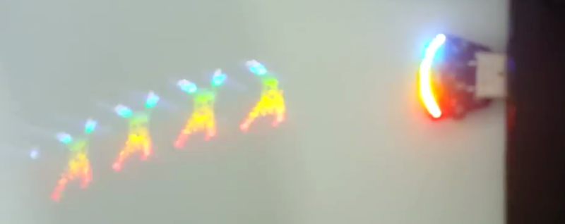
You think you’ve seen everything that there is to see regarding blinking LEDs and then a simple little trick proves you wrong. Our friend [Zach Fredin], aka [Zakqwy], added a pander mode to his blinky board which shows the Hackaday Jolly Wrencher in a Persistence of Vision mode. We love pandering, and obviously you just need to start the mode and wave the board back and forth. But in thinking the obvious you’d be wrong.
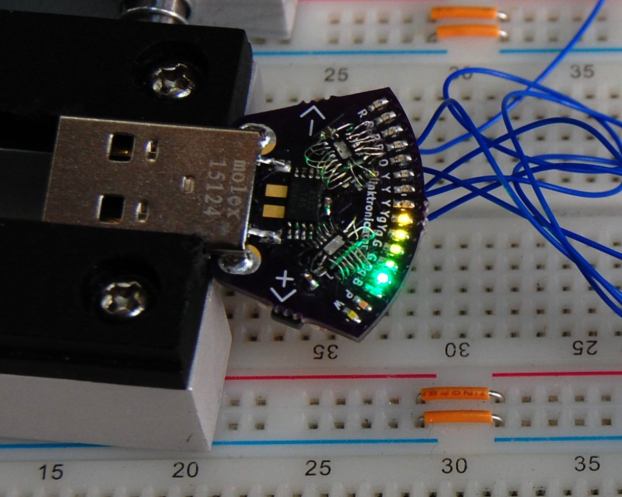
In the video after the break [Zach] demonstrates all the features of the blinktronicator and it’s recently finalized firmware. The tiny little board is a USB dongle featuring two buttons and an arc of sixteen LEDs in a rainbow of colors. When we say tiny, we mean it. Those LEDs are 0402 components and the board was small enough (and interesting enough) to receive an honorable mention in the Square Inch Project.
You would think that soldering all those LEDs by hand would be the trick, but [Zach] pulled off a much more difficult feat. Look closely at the image here (or click to embiggen). The two shift register footprints on the prototype were mirrored. He deadbug soldered each of them using — get this — the individual strands from some 28 AWG stranded wire. You sir, get the hardcore hand soldering badge and then some.
Okay, we’ll stop beating around the bush. The ATtiny45 on this board isn’t connected to the USB data lines, they’re only for power. That means, at its heart this is purely a blinking LED project, albeit one that uses the huge range of colors of the PICOLED family of parts. [Zach] did well with just two user inputs, but it’s the very simple POV party trick that really sucked us in. Instead of waving the board around, [Zach] uses a metal offset spatula as a mirror. Moving it back and forth unfolds the carefully timed flashes to draw your message in the air. Such a simple concept, but so satisfying to see it applied in a slightly different way.


So what’s it purpose besides being cool?
It makes you ask this definitely useless question and makes me answer it.
It serves a vague purpose to help me select indicator LED colors for other projects. And, uh, looks cool.
Burn!
But seriously, the one-of-each-color LEDs is a great idea.
Good enough for me, I’ll take a dozen.
I think it would be interesting to do this with several different brands or types of ‘white’ LEDs.
Got that suggestion from Dave among other folks on the HaD.io page–definitely something I’m thinking about. Will need an updated PCB, as part of the fun of ‘white’ LEDs are all the different footprints. Fun!
Could he have moved the camera back and forth quickly to see the POV pattern? Would that work?
The scanning pattern of the camera might not have captured it, and also auto focus might not like it.
I like this device for some reason. (Besides the soldering skill!)
Didn’t work with my POS Galaxy S4 “video camera”, but maybe it would with a nicer setup. I was able to capture some decent shots with a DSLR.
Regarding those mirrored shit registers, surely it would have been easier to solder the parts upside down on the board directly, rather than bother with all those jumpers.
I had trouble bridging the ~1mm or so gap between the pads and the PCB when I just flipped the chips over. However, I also tried tombstoning one side and wiring the other terminals, which proved to be much more robust than the upside-down hovering chip method shown above: https://cdn.hackaday.io/images/3594911451282631556.JPG
ahh… the upside down components… everyone who designs a PCB sooner or later goes through this stage. And if you are etching your own PCB then sometimes you need to do this for all components :( Been there done (that more then once) and every time I could laugh about it. So thanks for sharing this with us.
I think that when I noticed the shift register issue I would have sighed deeply, respun the board and waited a couple weeks for the new corrected one to arrive. I dead-bug things at work all the time but that was pretty extreme. Kudos for just making it work
I didn’t realize it was even POSSIBLE to hand solder at that scale! I find myself wondering if we are in the presence of a soldering wizard.
I assumed a wizard as well. I’ll never be near that good, lol.
I met Zach once. Can confirm: wizard.
Wut, no knight rider / cylon back-and-forth mode?!? Fail, clearly…