Hackaday Prize Entry: DIY Foot Orthotics

What does your gait look like to your foot? During which part of your gait is the ball of your feet experiencing the most pressure? Is there something wrong with it? Can you fix it by adding or removing material from a custom insole? All these answers can be had with an expensive system and a visit to a podiatrist, but if [Charles Fried] succeeds you can build a similar system at home. 

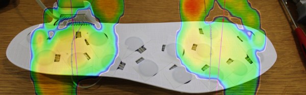
The device works by having an array of pressure sensors on a flat insole inside of a shoe. When the patient walks, the device streams the data to a computer which logs it. The computer then produces a heat map of the person’s step. The computer also produces a very useful visualization called a gait line. This enables the orthotist to specify or make the correct orthotic.

[Charles]’s version of this has another advantage over the professional versions. His will be able to stream wirelessly to a data logger. This means you can wear the sensor around for a while and get a much more realistic picture of your gait. Like flossing right before the dentist, many people consciously think about their gait while at the foot doctor; this affects the result.

He currently has a prototype working. He’s not sure how long his pressure sensors will last in the current construction, and he’s put wireless logging on hold for now. However, the project is interesting and we can’t wait to see if [Charles] can meet all his design goals.

The HackadayPrize2016 is Sponsored by:

Blinktronicator’s POV Sends Our Eyebrows Rocketing Skyward

You think you’ve seen everything that there is to see regarding blinking LEDs and then a simple little trick proves you wrong. Our friend [Zach Fredin], aka [Zakqwy], added a pander mode to his blinky board which shows the Hackaday Jolly Wrencher in a Persistence of Vision mode. We love pandering, and obviously you just need to start the mode and wave the board back and forth. But in thinking the obvious you’d be wrong.

blinktronicator-board
Badass deadbug soldering to “fix” a mirrored shift register footprint

In the video after the break [Zach] demonstrates all the features of the blinktronicator and it’s recently finalized firmware. The tiny little board is a USB dongle featuring two buttons and an arc of sixteen LEDs in a rainbow of colors. When we say tiny, we mean it. Those LEDs are 0402 components and the board was small enough (and interesting enough) to receive an honorable mention in the Square Inch Project.

You would think that soldering all those LEDs by hand would be the trick, but [Zach] pulled off a much more difficult feat. Look closely at the image here (or click to embiggen). The two shift register footprints on the prototype were mirrored. He deadbug soldered each of them using — get this — the individual strands from some 28 AWG stranded wire. You sir, get the hardcore hand soldering badge and then some.

Okay, we’ll stop beating around the bush. The ATtiny45 on this board isn’t connected to the USB data lines, they’re only for power. That means, at its heart this is purely a blinking LED project, albeit one that uses the huge range of colors of the PICOLED family of parts. [Zach] did well with just two user inputs, but it’s the very simple POV party trick that really sucked us in. Instead of waving the board around, [Zach] uses a metal offset spatula as a mirror. Moving it back and forth unfolds the carefully timed flashes to draw your message in the air. Such a simple concept, but so satisfying to see it applied in a slightly different way.

Continue reading “Blinktronicator’s POV Sends Our Eyebrows Rocketing Skyward”

Horrible Macro Rig Makes Good Photos

We love horrible hacks like this. It’s a lens and a ring of LEDs, taped to a cell phone. Powered through crocodile clips, also taped to the cell phone. There’s nothing professional here — we can think of a million ways to tweak this recipe. But the proof of the pudding is in the tasting.

Continue reading “Horrible Macro Rig Makes Good Photos”

Wired Networking For The ESP8266

The ever popular ESP8266 is popping up in more and more projects. There are CNC controllers, blinkey WiFi lighting, and downright bizarre WiFi to Ethernet bridges. [Cicero] has thrown his hat into the ring with one of these Ethernet-enabled ESP8266 builds, and right now everything works, it’s simple to put together, and cheap to build.

Astute readers will notice we’ve seen something like this before. A few months ago, [cnlohr] discovered the Ethernet controller in the ESP8266. This was, by every account, the hard way of doing things. [cnlohr] was driving the Ethernet directly through the ESP’s I2S bus. [Cicero]’s project does not. It uses the cheap ENC28J60 SPI to Ethernet adapter to put the ESP on a wired network. Is one solution better than the other? That’s arguable. Is one solution much simpler than the other? Yes, [Cicero]’s work allows anyone to add Ethernet to the ESP8266 with a few resistors and a module that costs $3 from the usual online shops.

With the Ethernet stack taken from [Ulrich Radig], the SPI driver from [MetalPhreak], and an ESP8266-based web server from [Sprite_tm], [Cicero] managed to serve up web pages through both the wired and wireless connections.

Although this build is not as technically amazeballs as [cnlohr]’s work with driving Ethernet directly from the ESP, it is very easy to implement, opening up the doors to a few of the more interesting capabilities of a wired ESP. With the Ethernet unlocked, there’s a free WiFi interface to wardrive, snoop around in promiscuous mode, inject packets, bridge a bunch of ESPs in mesh mode to another network, and other network shenanigans. The ENC28J60 modules have probably already found their way into a few parts bins and junk boxes already, making [Cicero]’s work the quick start guide to wired networking on the ESP.

Thanks [PuceBaboon] for sending this one in.

Interactive WeddingBots Built Into Nespresso Capsules

Today is a very special day for [Mandy and Sebastian], as they conclude the sacred solder joint of marriage. We send our sincerest congratulations and best wishes to the bridal couple, and can’t help but envy the guests of their ceremony, who received a very special wedding favor: A WeddingBot.

img_3337For their wedding party, [Mandy and Sebastian] created a little game on their own (translated). Each guest would receive a unique, little WeddingBot. Each of these is individually tailored for a certain guest and features a fitting look, a characteristic behavior and would play a special melody or jingle meaningful to this guest. However, the guests don’t get their WeddingBot, they get the WeddingBot of another guest – and the challenge to find this guest on the party. Guests would then exchange their WeddingBots, which also makes a great occasion to introduce themselves to each other. If the clues given by the WeddingBots themselves would not suffice to find the right owner, guest could place a WeddingBot on a clue station, which then would provide further hints by displaying images, texts or even riddles.

The design is based on the ATtiny45 microcontroller, with LEDs for the eyes, a light sensor, and a piezo disc for the sound as the main components. As an enclosure, they chose to repurpose empty Nespresso® capsules, which look nice and adds volume to the PCBs. The smiley face silk screen on the PCBs was then individualized with a black marker and packed in a beautiful hand-crafted box. The little fellows communicate with the Raspberry Pi based clue station by flashing their LEDs in a certain pattern. A light sensor hooked up to the Pi lets the station identify the bot and display the corresponding clue on a screen. Check out the video below to see how it works:

Continue reading “Interactive WeddingBots Built Into Nespresso Capsules”

What Could Go Wrong: SPI

Serial Peripheral Interface (SPI) is not really a protocol, but more of a general idea. It’s the bare-minimum way to transfer a lot of data between two chips as quickly as possible, and for that reason alone, it’s one of my favorites. But that doesn’t mean that everything is hugs and daffodils. Even despite SPI’s simplicity, there are still a few ways that things can go wrong.

In the previous article in this series, inspired by actual reader questions, I looked into troubleshooting asynchronous serial connections. Now that you’ve got that working, it’s time to step up to debugging your SPI bus! After a brief overview of the system, we’ll get into how to diagnose SPI, and how to fix it.

Continue reading “What Could Go Wrong: SPI”

SpotMini Struts Its Stuff

Boston Dynamics, the lauded robotics company famed for its ‘Big Dog’ robot and other machines which push mechanical dexterity to impressive limits have produced a smaller version of their ‘Spot’ robot dubbed ‘SpotMini’.

A lightweight at 55-65 lbs, this quiet, all-electric robot lasts 90 minutes on a full charge and boasts partial autonomy — notably in navigation thanks to proprioception sensors in the limbs. SpotMini’s most striking features are its sleek new profile and manipulator arm, showing off this huge upgrade by loading a glass into a dishwasher and taking out some recycling.

Robots are prone to failure, however, so it’s good to know that our future overlords are just as susceptible to slipping on banana peels as we humans are.

Continue reading “SpotMini Struts Its Stuff”