Adjust the phase current, crank up the microstepping, and forget about it — that’s what most people want out of a stepper motor driver IC. Although they power most of our CNC machines and 3D printers, as monolithic solutions to “make it spin”, we don’t often pay much attention to them.
In this article, I’ll be looking at the Trinamic TMC2130 stepper motor driver, one that comes with more bells and whistles than you might ever need. On the one hand, this driver can be configured through its SPI interface to suit virtually any application that employs a stepper motor. On the other hand, you can also write directly to the coil current registers and expand the scope of applicability far beyond motors.
Last month, we took a closer look at microstepping on common stepper driver ICs, but left out the ones that we actually want to use: the smart ones. Trinamic provides some of the smartest stepper motor drivers on the market, and since the German hacker store Watterott released their SilentStepStick breakout boards for the TMC2100 and TMC2130, they are also setting a new standard for DIY 3D printers, mills and pick-and-place robots. I recently acquired a set of both of them for my Prusa i3 3D printer, and the TMC2130 with its SPI configuration interface really caught my attention.
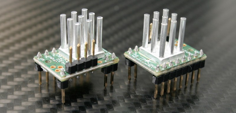
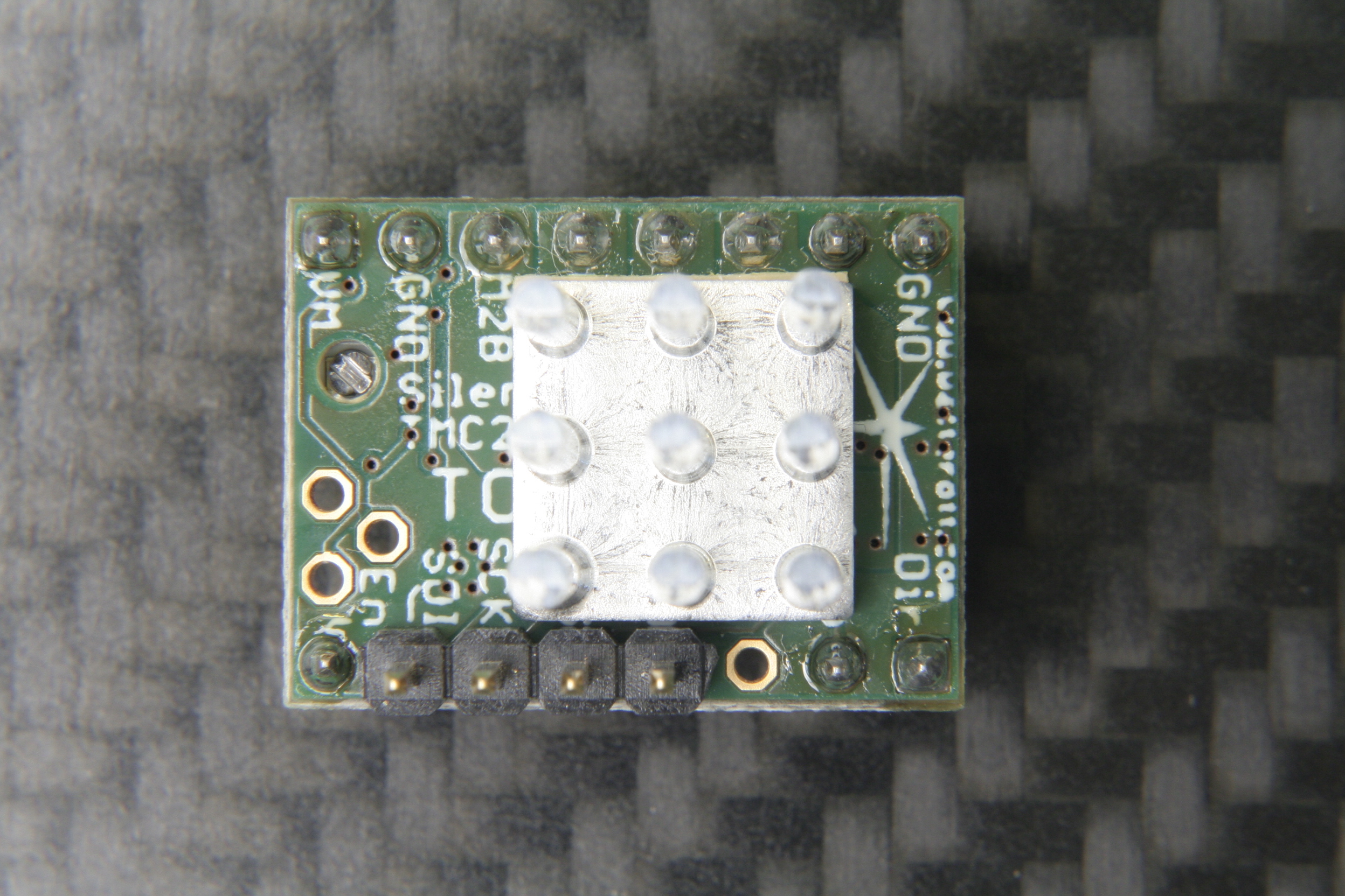
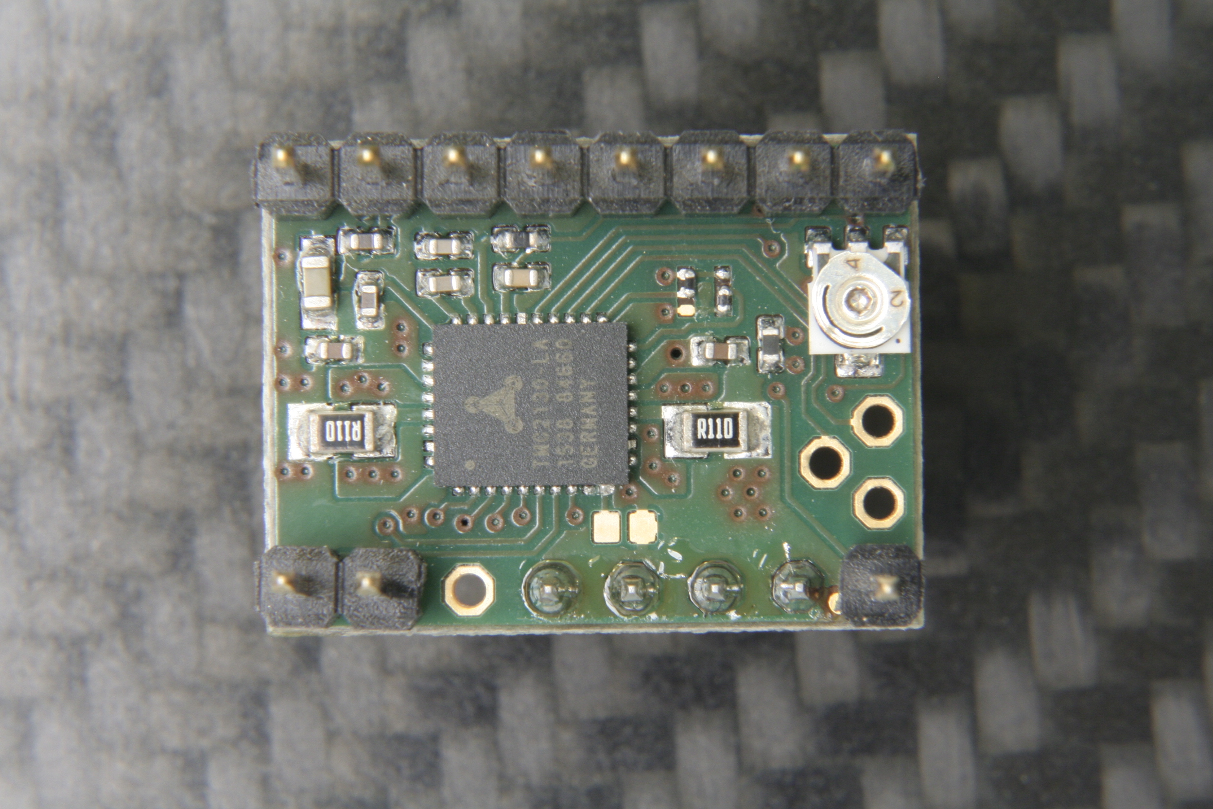
The TMC2130 SilentStepStick should not be confused with the — far more popular — TMC2100 variant. As the name suggests, it comes as a StepStick-compatible breakout board, and just like it’s famous sibling, features a Trinamic IC on the bottom side of the little PCB. Several vias and copper spills conduct heat away from the IC’s center pad, allowing a heatsink on the top side to effectively cool the driver.
However, unlike the TMC2100, this one won’t let your motors spin right away. You’ve got two options: Hard-wire it in stand-alone mode, which practically turns it into a TMC2100, or hook up to its SPI-interface and dial in if you want your stepper motor shaken or stirred. In fact, plentiful configuration registers make the TMC2130 an extremely hackable chip, so I’m not even thinking about bridging that solder jumper on the SilentStepStick’s bottom side that activates the stand-alone mode.
First Steps

As said, before the driver does anything, it wants to be configured, and it’s worth mentioning that all configuration registers are naturally volatile, so if I want to use them in my 3D printer, I need to configure them as part of the printers startup routine.
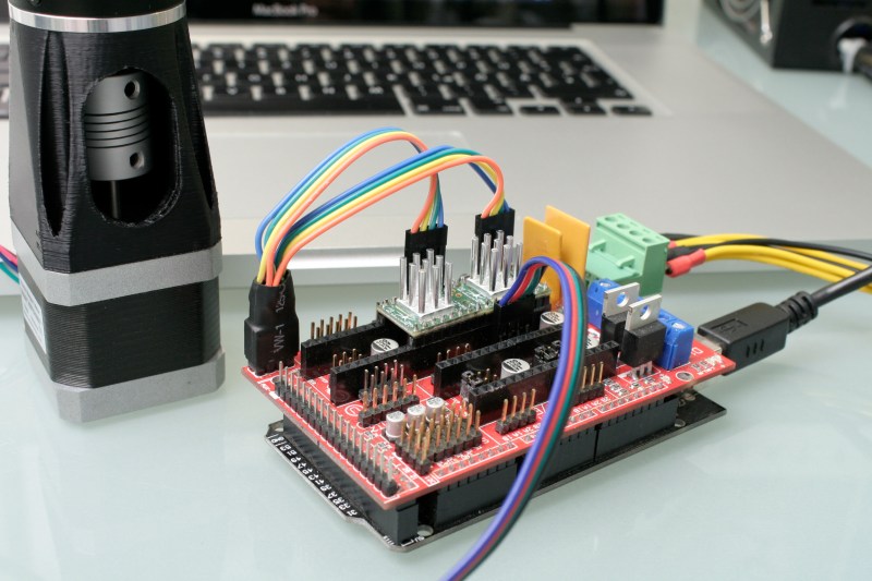
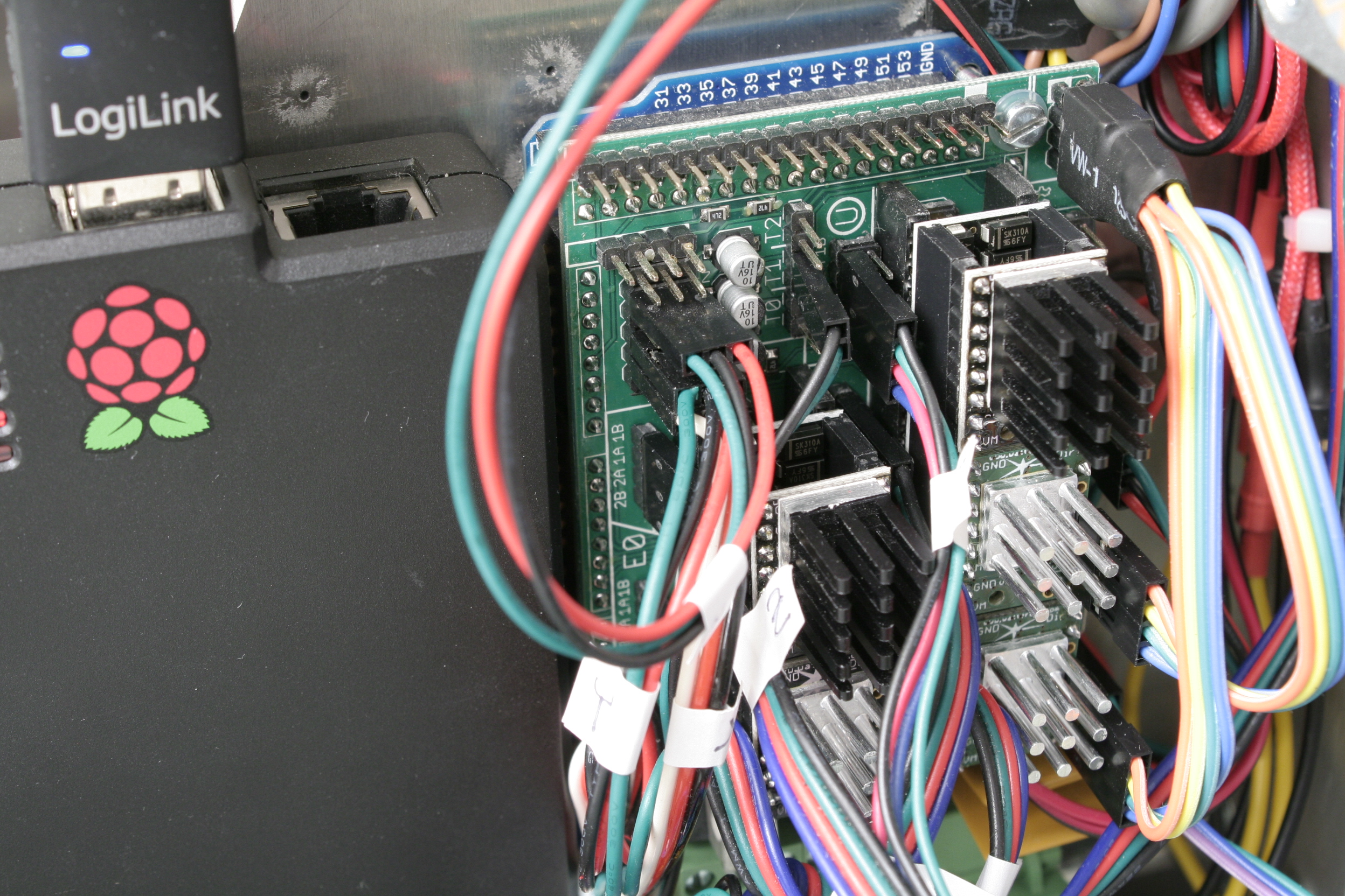
The RAMPS 1.4 on my 3D printer breaks out the hardware SPI interface of the underlying Arduino through its AUX3 pin header, along with two additional digital pins (D53 and D49), which I used for the cable select signals. After crimping a cable to connect two TMC2130’s to the AUX3 header, I could start digging into the software part.
Watterott provides an example sketch, which writes a basic configuration to the driver’s registers and spins an attached stepper motor. Great stuff, but the datasheet describes 23 configuration registers waiting to be finely tuned, and 8 more to read diagnosis and status data from. So, I wrote a little Arduino library that would make the numerous configuration parameters available in a more practical way. From there, I could just include my library into the Marlin-RC7 3D printer firmware I’m using. Luckily, the current Marlin release candidate already features support for TMC26X drivers, so I could reuse some of its code to put together a Marlin fork that includes 59 of the TMC2130’s parameters in its define-based configuration files. And then, I could take the little buddies out for a spin.
Taking Them For A Spin
With the hardware set up and the software working as supposed, I ran a few sanity tests: toggling parameters on and off and checking how the driver’s behavior changes during printing. Since the TMC2130 let’s you tune almost everything it’s doing, that’s a good first step that helps to eliminate some variables and picking others that are worth a deeper look. Most of the settings can be changed on the fly and mid-print, however, not all parameters can actually be safely changed while the motors are running.
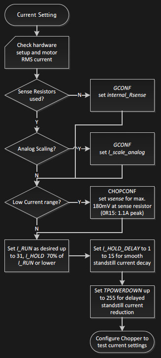
To actually tune the drivers for a certain application, Trinamic provides a quick start guide in the datasheet, as well as detailed information on each parameter, and on how they interact. Basically, the first step is adjusting the RMS coil current by using the onboard potentiometer on the SilentStepSticks. Then, we need to chose the analog input pin as a current scaling reference to actually make use of the potentiometer. The mentioned library lets me do this through a simple method:
myStepper.set_I_scale_analog(1); // 0: internal, 1: AIN
The running and holding current are the first real parameter that should be tuned, with the running current typically at the desired maximum current, and the holding current at 70% of this value. The delay between a stillstand and the transition from running current to holding current can be adjusted between 0 and 4 seconds, and for now, I set it to 4 seconds, practically disabling the current reduction while the 3D printer is running. The three values share one write-only register, so the corresponding method call looks like this:
myStepper.set_IHOLD_IRUN(22,31,5); // [0-31],[0-31],[0-5]
and sets the running current to 100% (≙ 31), the holding current to about 70% of this value (≙ 22), and the delay between the two to 4 seconds (≙ 5).
I want torque, so I can leave stealthChop disabled. The datasheet suggests some starting values for configuring the chopper’s off time and the comparator’s blank time settings, but since it’s a key tradeoff between switching noise and torque, it makes sense to iterate through other values as well. The library methods for the two values look like this:
myStepper.set_tbl(1); // [0-3]
myStepper.set_toff(8); // [0-15]
And finally, I need to pick a microstepping resolution and choose if I want to make use of the 256 microstep interpolation feature, covered later in this article:
myStepper.set_mres(32); // {1,2,4,8,16,32,64,128,256}
myStepper.set_intpol(1); // 0: off, 1: interpolate
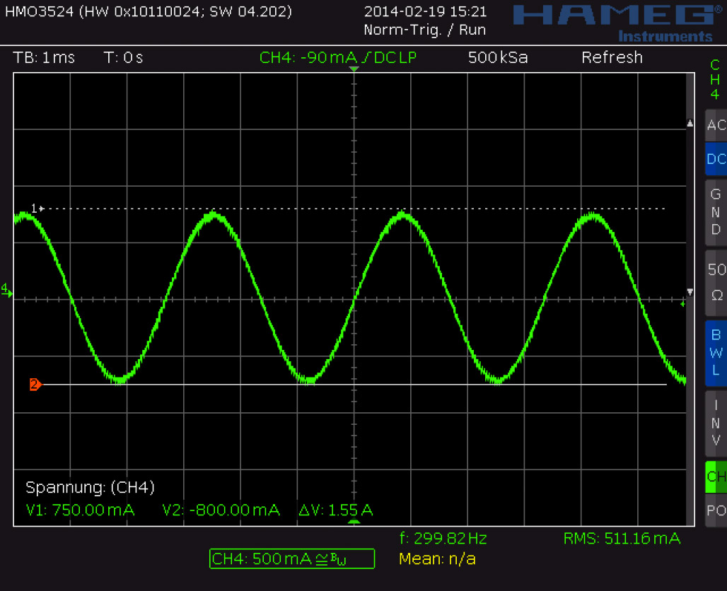
I have yet to walk through the entire tuning procedure, which includes monitoring the coil current on the scope and eliminating distortions in the zero crossing, but I’m getting a clue of the driver’s potential.
Juice
It’s maximum continuous RMS current of about 1.2 A per coil (at least in the QFN package on the SilentStepSticks) lets it look like a low-current driver, inferior to the common A4988 and DRV8825. In practice, it outperforms both of them by making intelligent use of a 2.5 A peak current margin. This gives it more than enough torque for 3D printing. I wouldn’t recommend pushing them over 0.9 A RMS though since the IC will momentarily pull more current if it needs more. For SilentStepStick users, that’s a Vref of 0.88 V. Through the SPI-interface, you can choose how much current you want to send through the motor coils when it’s spinning, and when it’s idling. You can choose after how many seconds it will start to decrease the current to a lower holding current when the motor is in standstill, and then to an even lower idling current. And, of course, you can also set it to squeeze out the maximum juice for everything.
Shifting The Gears
Where it starts getting interesting are settings like the high-velocity mode. Above a configurable velocity threshold, the driver offers you to automatically switch the chopper to a faster decay time to squeeze out some extra speed. You can also literally shift the gears by letting the driver internally switch from microstepping to full-step mode once it’s up to speed.
Microstepping
Choosing a finer microstepping resolution smoothens the stepper’s movement, reduces vibrations and sometimes even increases the positioning accuracy. However, it also multiplies the load on the microcontroller, which has to churn out 16, 32 or 256 times more step pulses per second. The TMC2130 lets you pick an input resolution between 1 and 256 microsteps per full-step, and then gives you the option of interpolating the output resolution to 256 microsteps. This allows for smooth operation even on increasingly retro 8-bit AVR motion controllers, which cannot deliver high step frequencies. Also, by configuring the TMC2130’s interface to double-edge step pulses, you can at least double the step frequency at almost no cost. Given that the modern IC still features the classic step/direction interface and even an enable pin, those few additional features actually make it a sweet drop-in upgrade for less-recent CNC and 3D printer electronics.
Noise Reduction
Just like the TMC2100, the TMC2130 features two efficient and silent drive modes: spreadCycle, and stealthChop. The former delivers high torque at relatively low noise emissions, the latter one is almost inaudible, and there are quite some confusions out there about whether or not that affects torque: Some users experience dramatically reduced torque, while Trinamic’s paper on the issue states the opposite. Below 300 RPM (typical 3D-printing speeds), stealthChop should not affect torque at all. According to Stephan Watterott, double- and quad-stepping, as used in most 3D printer firmwares, could be to blame here.
Either way, the flexible TMC2130 allows you to tweak the chopper yourself to find the right balance between torque, noise, and efficiency for your application. One of the more noteworthy options in this regard is the possibility of randomizing the chopper’s off time. Since most of the audible noise is released due to dubstep the chopper busily switching the stepper motor’s coils, this option spreads the noise over a wider frequency range to subjectively silence the stepper motor.
Stall Detection
The TMC2130 notices when the motor is stalled and losing steps by measuring the motor’s back EMF. Along the way, it counts missed steps, allowing the controller to compensate for otherwise irreversible step-loss. It’s also a great way to react to obstacles rather than running into them full-force and, of course, the feature can be used as an axis endstop. Trinamic calls this feature StallGuard, and just like anything else in this motor driver, it’s highly configurable.
Direct Mode
 Instead of letting the motor driver handle everything for you, you can also choose the direct mode. This mode practically turns the driver into a two-channel, bipolar constant-current source with SPI interface. You can still use it as a motor driver, but the possibilities reach far beyond that. It’s worth mentioning that the datasheet might be a bit confusing here, and the corresponding XDIRECT register actually accepts two signed 9 bit integers (not 8 bit) for each coil and operates as expected within a numeric range of, naturally, ± 254 (not ± 255) to vary the current between ± Imax/RMS..
The Takeaway
About half a year after the release of Watterott’s breakout board, the potential of smarter stepper motor drivers piqued the curiosity of the 3D printing community, but not much has happened in terms of implementation. Admittedly, it takes some effort to get them running. If you’re still busy dialing in the temperature on your 3D printer, you surely don’t want to add a few dozen new variables, but if you’re keen on getting the best out of it, the TMC2130 has a lot to offer: low-noise printing, high-speed printing, print interrupt on failure and recovery from lost steps. Because the driver IC is so hackable, it’s clearly intended to be tuned in to accommodate specific applications. Throwing it on a general purpose test bench probably won’t yield meaningful, general purpose results.
I hope you enjoyed taking a look at a smarter-than-usual stepper motor driver, as one of the new frontiers of DIY 3D printing, and as an interesting component with many other applications. If you’re thinking about experimenting with this IC or breakout board in your 3D printer, feel free to try my Marlin fork to get started. If you’re building something entirely different, the underlying Arduino library will help you out. Who else is using this part? I’ll be glad to hear about your ideas, applications, and experiences in the comments!


For reliability, find a way to ziptie or screw those boards down, anything that thermal cycles in a socket will walk itself out of it.
So curiosity is driving me up a wall, did the encoder show a gain in effective resolution beyond half stepping?
I think the TMC2130 has this feature, but unfortunately the SilentStepStick doesn’t break out the IC’s encoder pins. I’m exploring ways to test the dynamic positioning accuracy using the encoder, but for now, I’ve just been using the encoder to verify proper operation of the library.
Figures. It is on my list to (one of these days) make a breakout board for these and take ’em for a spin so to speak, thanks for the great write up.
Well, it kind of breaks them out to tiny configuration pads (equipped with zero ohms), so with help of a bit of magnetic wire you should be able to use the encoder commutation feature on the SilentStepSticks as well. But I’m not sure if this is meant to increase resolution.
Dead end, see below..
I’ve emailed Trinamic about the vague notes in the datasheet that allude to encoder support. They say to basically forget about it, it doesn’t really apply to the TMC2130, it was either a datasheet copy and paste error, or something they put in for a specific customer but either way, they assured me it wasn’t possible on the TMC2130.
Bloody shame, really.
Interesting, I emailed them, too, and received an entirely different response: They said the feature were some sort of free-running mode. Once a full-step encoder is attached and the configuration flag is set, the stepper motor would just spin as fast as it can (basically, what’s stated in the datasheet). I’m still clueless about what this would be good for..
Either way, if you want to close the loop, you’ll have to do it externally. Too bad.
I’m intrigued by the TI chips that auto-tune, though its current rating is a bit low.
http://www.ti.com/product/drv8885?DCMP=drv888x&HQS=hval-mdbu-amd-drv888x-pr-pf-vanitydrv8885-wwe
@moritz, would you consider doing one of your excellent write-ups on those chips?
No doubt TI’s adaptive blank time adjustment is a nice feature. Might actually be interesting to see how it affects noise, torque, and speed.
Damn, it’s been awhile since I commented on here, but I’m loving the stepper driver stuff lately. Would love to see the series continue, with super in depth analysis and test methodology. Not enough of this stuff exists on the open web right now IMHO.
Bravo, great article!
Well the “low” current really isn’t a problem in my opinion. Running a motor at the current shown on the label cause them to get alarmingly hot. I think it’s either an absolute maximum or the current on my RAMBo is really an RMS figure. I think I’m running my motors at half the current shown in the motor specs and getting excellent results from them. FWIW, I’m not actually getting any more than 1A out of an A4988, much more and they can start acting up.
Isn’t 1A the datasheet stated max for them?
Great article! I’d like to know how do these compare to the other steppers in the recent comparison?
I also want to see someone do something with these and encoders, hope to see it here soon!
Thanks!
As said, these drivers are meant to be tuned to a certain application, with their performance depending on a few dozen configuration parameters. Throwing general purpose tests at them (like the positioning test last month) probably won’t yield a meaningful result.
But I think we need to look into this encoder commutation feature a bit more.
First off, you’ve done an amazing job on these stepper driver articles. Awesome work!
While it’s true that the TMC2130 offers lots of room for configuration, I think the configuration that most 3D printer users would be interested in would be the TMC2100 in spreadCycle mode and 1/16 microstepping with interpolation to 1/256 microstepping. I know that a *lot* of people would be interested in seeing this configuration compared to the other stepper drivers you wrote about in the other article. Is that something you would be willing to consider?
Thanks for these articles and keep up the good work!
Thanks! I’m hearing you! I’m working on a test that will address this. These things take time!
I’d just like to add to the chorus and say that the TMC2130’s are legit. I’ve used them and they’re definitely worth the extra time to get them setup properly.
“According to Stephan Watterott, double- and quad-stepping, as used in most 3D printer firmwares, could be to blame here.”
Can I have a source link on that information please ? I’d like to read the full text of what Stephan W. says about this.
Thanks.
Well, he told me in an email. Here’s what he said:
“Hallo,
Ich glaube das Feature wurde aus dem Datenblatt entfernt, es gibt keine Infos dazu.
Vermute das dies nicht richtig geht.
Was vielleicht noch interessant für dich ist: http://www.trinamic.com/_scripts/download.php?file=_articles%2Fproducts%2Fintegrated-circuits%2Ftmc2130%2F_appnotes%2FAN021-stealthChop_Performance_comparison.pdf
Das Drehmoment ist bei spreadCycle und stealthChop fast gleich, die Probleme mit den Schrittverlusten treten hier häufig im Zusammenhang mit double und quad Stepping auf.
Mit freundlichen Gruessen / Best Regards
Stephan Watterott
– CEO -“
Hi Moritz,
as a complete noob running two printers at this time, you encouraged me to finally rebuild / modify my Leapfrog Creatr and Ultimaker Original +. Without you article, I would be totally lost I guess. :-)
I have to modify them, because I really get sick of all the noise they make, so I decided to buy two RAMPS 1.4 sets as well as the TMC2130 modules for all 3 axles (including the protection boards) from Watterott.
Beside all the other problems I have now (electrical wiring of RAMPS etc) I have one critical question:
In my RAMPS 1.4 packages, a full graphic display was included to connect to the board. The SPI interface you mentioned here would be already blocked by the adapter for the display. Can there be multiple devices on that SPI??
I do not want to leave out the display although I will be using Octoprint as well.
If there is a possibility, do I have to regard any specialties?
Thank you so much in advance.
Markus
Hi, and sorry for the late reply!
Sure, you can have a display and all three stepper motor drivers on a RAMPS. All devices will share the CLK and SDI/SDO pins, all you need is find some free CS pins on your ramps and solder an adapter that connects the three stepper drivers to the CS pins and the RAMPS’s (i.e. Arduino Mega’s) hardware SPI interface.
Hope that helps!
Best,
Moritz
Easy question, Where can I find those protection diode shields you are using for the drivers?
They look like these: http://www.watterott.com/en/SilentStepStick-Protector
You will find them at http://www.watterott.de
Anyone get the TMC2130 into the dcStep mode? I’ve been working through the documentation and coding and have stalled out :) on that one. Also curious whether anyone has tried the 5130. Thanks!
How could I get these drivers working with all features if I am using a Re-ARM controller with a RAMPS board running Smoothieware?
Did you ever set up and investigate StallGuard? I took a look at the code and it doesn’t look like it is. Is there a specific reason it wasn’t or you just ran out of time? Also just a warning to anyone wanting to use these the 49 and 53 pins on AUX 3 are also assigned with the SD card reader so you might have to use other pins
I’m very new to reprap, but I’m running 2130s and for X & Y I have the DIAG0 wired to the corresponding limits. I’m unaware of any additional special coding being required to use stallguard. I could be wrong, though. My X is effortless, but I do experience some hammering on the Y axis ends on occasion.
Many sellers ship the TMC2130 StepStick with no config solder blobs at all. This leaves them ready for advanced configuration via SPI. Do CFG4 and CFG5 need to be soldered to GND and VIO respectively if configuring via SPI?
Sorry if the question is silly but I couldn’t understand how can we use the lcd when the tmc2130 drivers are on the ramps board since the lcd screen also uses those spi pins.
@dtserkanozkan I also asked that and he replied to that answer. But I also have no idea, what to configure where…. :-( Moritz told me to find other Digital pins for CS of the drivers but I do not know which ports to use and what to change in pins_RAMPS.h.
Maybe someone else can give us two a helpful hint for starters? :-) Thanks in advance!
Could someone give me some hints on how to wire the TMC2130 to a Rumba board?
Is possible to use the Miso/mosi/Sck ports of one of the two ISP ports and configure the remainign pins on the exp3 port?
Any help is deeply appreciated! Thanks!
I am also needing to connect tmc2130 to the rumba board and am not finding the SPI pins.
For Rumba, you need to use the EXP2 connector. You will find the pins of this connector here : https://raw.githubusercontent.com/Aus3D/RUMBA-Plus/master/Images/pinOut.png
Plugging SCK, SDI (MOSI), and SDO (MISO) is pretty straight forward. As for CS_X, it goes to D53 and CS_Y goes to D49.
Next, in Marlin pins_RUMBA.h, you need to add this line :
#define X_CS_PIN 53
#define Y_CS_PIN 49
If you use a LCD, I don’t know yet where else you can plug SCK, SDI and SDO and how to do it… Maybe ISP would work, I don’t know.
However, you can easily change the X_CS_PIN to D14 of EXP3 for example (and change Marlin to #define X_CS_PIN 14).
If I find a way to change the SCK, SDI, SDO pins (I also have a LCD that I would like to keep!), I will keep you in touch
Hi Jacques D
Did you found any solution how to keep LCD working and get TMC2130 on rumba ?
I was thinking of using digital pins on EXP3 is it posible ?
Can you contact with me somehow ?
lol for those MOSI MISO SCK pins we can use ISP1 programming port :) 6 pin ISP1 so LCD will work
so where to connect separate cables from stepper drivers maybe on EXP3 ?
Hello,
I made this by your guide especially i downloaded the TMC 2130 drivers via th arduino version 2.1.1.
But when i connect the pins like on your picture, i got these errors. X driver error: overtemperature, and short to ground coil A and coil B (i got this error messages on every stepepr drivers). When i dont connect those pins on your picture the steppers can work and my printer print and i set up the voltage on the stepper driver current to 0.6V .On this current my stepper drivers temperature is way too high, and they are going to skips moves.
I have a ramps 1.4.
That’s most likely you connected SDO to MOSI and SDI to MISO if you swap the pins your problem is solved!
Paul
Good night, my friend, I would like a help, it is possible to use this TMC 2130 drive and the Discount Full Graphic Smart Controller if possible, have some photos of how it can be done and in marlin 1.1.8 what will be the changes? Thank you for your help !!!
Since the aux header you need is covered by the board, you can either solder headers to the back of the LCD board’s pins, or run leads from the ICSP programming port on the MEGA under the RAMPS board (if you are using MEGA+RAMPS), then reassign the CS pins in pins_.h file to whatever you have available. The Marlin bug fix branch hints at simpler software assignment options in the future too, so keep an eye out on that when it makes it’s way into stable branch.
Soldering the three wires to the back of the LCD connector board is a terrible solution, but that’s how I have mine working at the moment. I just looked up the LCD wiring and found that the EXP2 10-pin ribbon cable carries the SPI lines we need. Simply installing a ribbon cable and connector onto the EXP2 cable will allow us to tap into those three lines. Ribbon connectors don’t have to be installed at the end, after all.
I mean, cool… but what if I want to keep my screen and SD? That’s the big clincher for me. I’ve yet to find instructions that show how/if you can use different pins…
It’s actually quite easy in theory, but annoying in practice to do this. What I did was solder the three SPI lines onto the back of the connector board – one to each of the SPI pins that are on AUX1. When moving things around a lot, I had a few times where a wire broke there. I was looking for a better approach but never revisited it because it’s been working fine ever since. There are two other options, I believe. The SPI bus is also accessable on the arduino board itself, in the center of the board. Well, that’s if you’re using arduino. If so, you can simply run your wires under the RAMPs baord, to the arduino. Finally, ribbon cables are simply connectors clamped onto the ribbon. Don’t overlook the fact that you can clamp additional connectors along the wire running from the connector board to the display, tapping into the SPI lines. Look at AUX1 and you will find the three SPI lines. SPI is a bus. The display, card reader and drivers all use it in parallel, so you’re just trying to tap into it. Let me know if you need more help.
Thanks dude, I’m somewhat familiar with SPI (was playing around with Arduino cameras) but good to hear someone else has done it and well spotted on the separate pin out on the Arduino Mega itself! That’ll probably be easiest for me as my electronics box is really cramped (24V supply, stepdowns, RAMPS, cabling and Raspberry Pi). I’m looking at getting the new Revolve board when it comes in, it’ll simplify my wiring a tonne but in the meantime I’ll be doing this.
I suppose one of the other methods would work better on the GT2560 motherboard. I’m using one in the Foldable Printer I designed.
I, too, have so much wiring that I’ve yet to figure out a box that can accommodate it all. At this point I think I’ll just leave the board as-is. The SPI chaning on the drivers was a PITA. My proof of concept used long wires, which was a mess. I was able to dramatically shrink it down by soldering each chained segment to the previous wire just above the connector. If you put two wires into one pin, you’d be unable to insert the pin into the connector far enough to lock. So imagine stripping the wire back ever so slightly and, after crimping the pin, wrap the next wire around the first wire, solder it and apply a short segment of shrink wrap. If you do it well, the pin will slide in and you can just barely get it to lock, with the wrap compressed right up against the connector. This will let you make short (less than 2″) hops from driver to driver.
Yikes! Sounds like a real headache… I’ve done similar before too and when I wanted to integrate all my hot end connectors into one block I ended up creating hoops between adjacent pins for the heater cartridge wires (to stay within the Dupont’s safety rating) and then linking thicker wires to those!
If you want to see messy wires hiding inside a neat electronics box, my YouTube channel is the place for you, hahah.
http://www.youtube.com/user/AcrimoniousMirth
In case you’re interested. Here is my prototype wiring harness. It used connectors with bridged standoffs to short all pins. I hope these links work…
https://drive.google.com/open?id=1rzHToe3w9u-LlkEcWKmoDWQjdAstdRFS3w
And here is v2.
https://drive.google.com/open?id=17jDKmViDbR3AewJVAL_N_FpIDd8HtyZk7Q
Very nice daisy-chaining! Thanks :)
updated datasheet URL:
https://www.trinamic.com/fileadmin/assets/Products/ICs_Documents/TMC2130_datasheet.pdf
If someone is fixing it, perhaps fix “it’s” and “let’s”.
A4988 drivers and I want to test the TMC2130 with the RAMPS 1.4. I know it doesnt make much sense for a CNC, but I want to try it. I am using 3 nema 1.7. In my actual CNC configuration I power the shield with 24 volts – 5 AMP power suply. What type of power suply should I use for the RAMPS 1.7 & 3 nema 17? Absoute beginner..;)
Tried OP’s makertum Trinamic_TMC2130 library, and found a bug:
read_STAT either doesnt work properly or some functions dont change value after being set,
i.e. changing set_I_scale_analog and set_en_pwm_mode only changes internal_Rsense bit??
Tried it with TMC2130Stepper live_tune test, everything works fine when cheking GCONF.
It’s a shame, really like that Trinamic_TMC2130 has its methods properly named according to the datasheet, unlike TMC2130Stepper lib.
Also, really great article, thanks for sharing your work :)