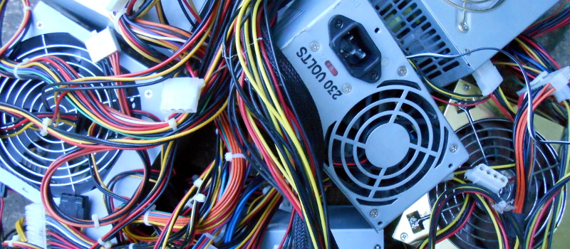
The PC power supply has been a standard of the junk box for the last couple of decades, and will probably continue to be for the foreseeable future. A product that is often built to a very high standard and which will give years of faithful service, yet which has a life of only a few years as the PC of which it is a part becomes obsolete. Over the decades it has evolved from the original PC and AT into ATX, supplying an ever-expanding range of voltage rails at increasing power levels. There have been multiple different revisions of the ATX power supply standard over the years, but they all share the same basic form factor.
So a pile of ATX supplies will probably feature in the lives of quite a few readers. Most of them will probably be old and obsolete versions of little use with today’s motherboards, so there they sit. Not small enough to ignore, yet Too Good To Throw Away. We’re going to take a look at them, try to work out what useful parts they contain, and see a few projects using them. Maybe this will provide some inspiration if you’re one of those readers with a pile of them seeking a purpose.
What’s Inside The Box?
![A typical ATX PSU schematic using a TL494. Dianyuan.com forum [Public domain], via Wikimedia Commons.](https://hackaday.com/wp-content/uploads/2016/10/1280px-tl494_atx_power_supply_schematic.gif)
The TL494 is a switched-mode power supply controller designed to work in a variety of configurations and manufactured by multiple semiconductor companies.
The basic operation of a switch-mode power supply is fairly straightforward, and ATX supplies have very few deviations from the norm. There is a mains rectifier and filter, a pair of high-voltage power transistors that switch the resulting DC at a few tens of kHz into a ferrite-cored transformer whose output is rectified to low voltage DC. The TL494 samples the output voltage and produces the PWM switching signal which is fed to the bases or gates of the power transistors through a drive transformer. There will also be a standby 5V supply using another small transformer, and a “power good” circuit to tell the motherboard that the PSU is ready and to activate the supply on an external input.
![A typical ATX PSU interior. Alan Liefting (Own work) [Public domain], via Wikimedia Commons.](https://hackaday.com/wp-content/uploads/2016/10/782px-atx_power_supply_interior.jpg)
A typical ATX PSU interior
Legend:
A: bridge rectifier
B: input filter capacitors, between B and C – Heatsink for HV transistors
C: transformer, between C and D – Heatsink for low-voltage rectifiers
D: output filter coil
E: output filter capacitors
Alan Liefting [PD], via Wikimedia Commons.
These supplies are slightly unusual in the age of surface-mount components, in that the majority of them you’ll find in a junk box still have through-hole construction. This makes them suitable targets for the electronic scavenger, as parts can more easily be retrieved intact. It’s worth taking a moment to look at the components you’ll find, and suggest some uses for them.
Parts, Parts, Parts
Most obvious when dismantling one of these boxes are the metal case, IEC connector, power switch, and fan. You shouldn’t need an explanation of how these could be reused, if you don’t mind a bit of steel drilling and your project case being obviously that of a PC power supply then they are very robust enclosures. The same goes for the wiring loom of motherboard and disk power connectors, a handy source of medium-sized hook-up wire.
If you look at the components on the PCB, many of them are standard discretes. Yes, we’ve all scavenged a 10K resistor at some point, but outside a few high-voltage capacitors in general they are not much to get excited about. So what is there on that board that’s worth lifting?
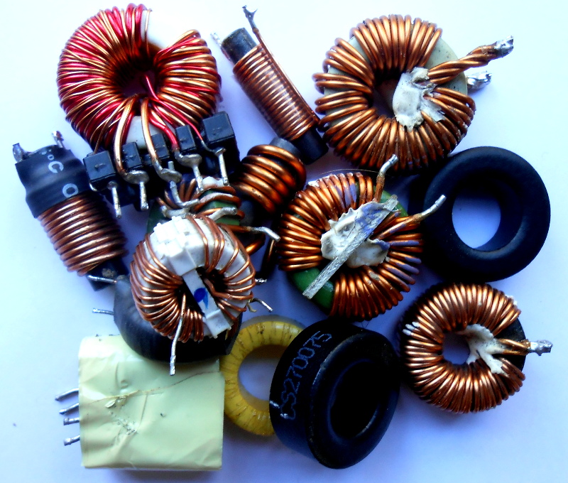
One thing that’s in abundance on an ATX PSU board are magnetics. Toroidal chokes and ferrite bobbins used in filters as well as the various ferrite cored transformers. The transformers are wound for the specific purpose so unless you have the patience to rewind them they may be of little use, but the chokes have more application. These are not exotic RF ferrites but more utilitarian iron-dust cores, though they still can find plenty of use wherever a choke is required. I’ve even used them as cores for co-ax baluns, when their purpose is simply to stop RF leaking down the feeder their poor RF performance is an asset. It’s also worth noting from an RF perspective that these chokes are also a handy source of plenty of heavy-gauge enamelled copper wire for your other inductors.
The semiconductors in an ATX PSU include some specialist components, but there are still alternative applications for them. On the high voltage side are a selection of high-voltage diodes and those switching transistors, all of which are a fertile source of parts if you are hacking together high voltage inverters. On the low voltage side apart from the TL494 or other controller chip you’ll find some high current rectifiers and more than one three-terminal 78XX series regulator if you are lucky, as well as in many cases a TL431 adjustable voltage reference. You may also find the various heatsinks to be useful in other projects.
Use It, Don’t Break It!
As you can see, an ATX PSU can yield some useful components. But since there is an almost limitless supply of them it’s not worth breaking one unless you need the parts, so what can you do with an intact one?
The answer is pretty simple: how about using it as a bench power supply? These supplies are not electrically the quietest or best regulated in the world, but they do have the advantage of providing several useful voltage rails at significant current levels. There is a small modification required to use one in this way, one of the lines is an enable line that is held high. Pull pin 16 low (usually a green wire) and the supply will start up. There are numerous projects on Hackaday.io showing how others have done this, and a quick search of OSH Park will yield a range of breakout PCBs like this one.
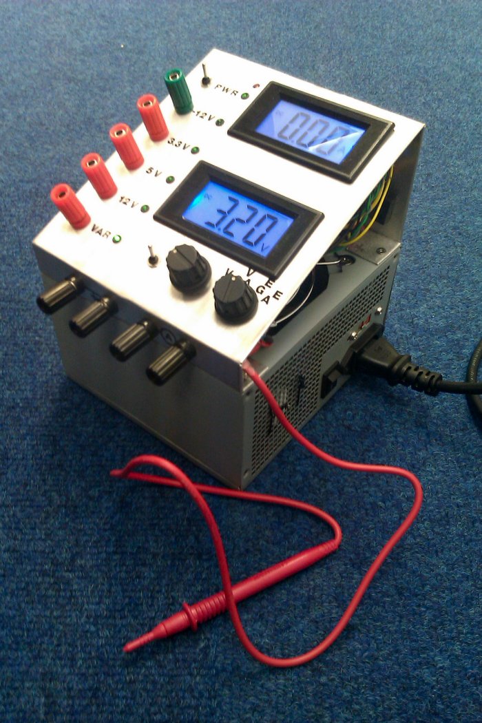
If fixed voltages aren’t enough, there have been many ATX bench PSU projects like the one pictured fitted with LM317 variable regulators on their 12V lines to provide an adjustable output. That is not the only way that this can be achieved though, the TL494 can be readily made into a variable regulator with a simple modification. The standard warnings and disclaimers apply with respect to the dangers of working on mains and high voltage equipment if you follow that route.
Of course, using a power supply as a power supply is all very useful, but it’s hardly groundbreaking even if it does sometimes involve a bit of hardware hacking. How about other uses for one? One area for which a supply capable of producing large currents might be suited for example is welding. It’s important to point out that by welding we do not mean the kind of welding you’d make ships or even cars out of, but that’s not the only place you’ll find a welder (This spot welder using just the case of an ATX supply is a fine project, but doesn’t quite count in this context). Last year for example we covered an ATX supply being used with a graphite electrode to weld thermocouples, providing a significant savings over commercial alternatives. And the metalworking potential of an ATX supply does not end there, you’ll find people using them for resistance soldering in the model making community.
So, you’ve still got that pile of metal bricks under the bench from all the old PCs that have come your way, but with luck after reading this you’ll have a bit of inspiration that may enable you to do something with them. Whatever you make be sure to share it with us on Hackaday.io, and don’t forget to send us the link!


Great post – I must have collected a dozen or so almost working 1Kw+ PSU’s, now all I need
is a 3-phase mains supply & a nice mig/plasma cutter/sprayer can be brought into existence :-)
Thanks for the post
Few tips:
* When you open it, do make sure the primary side capacitor(s) is discharged! Those puppies can charge up to 400V (with 240V mains) and they do pack quite a wallop! Many will keep a significant charge for a long time after the PSU was turned off. Touching one of these while charged will be an experience you likely won’t forget any time soon. Use a multimeter to check and a resistor to discharge the cap. DO NOT short it, as that could kill it, potentially causing a small explosion (and injury). Some multimeters have a low impedance mode (often marked “Low-Z” or similar), that is also good to safely discharge the caps.
* All European PSUs (and decent quality ones everywhere) will contain also a power factor corrector, usually another large coil/transformer-like thing with some electronics around. These are mandatory in EU since about a decade ago.
* If you want to reuse the PSU for a lab supply, the first thing to add should be a current limitter to the output. These things can deliver 20-40A on most of the rails without blinking (arc welders start in the same range …). While the supply is protected against short circuit (it will shut off), that will not prevent the creation of a pile of smoking plastic and molten slag if the short is a bit short of a complete short (pun intended). Also a major fire is possible. At the very least a resettable polyswitch fuse for each rail is a must, a better solution is an electronic adjustable regulator/protection.
* Don’t forget that the output of an ATX supply *is not* floating with regards to ground, unlike true lab supplies. That could be a problem in certain situations – e.g. an oscilloscope is also grounded and you could cause a short through the mains ground wire if you attach the grounding clip to the wrong point. With a true floating output supply it doesn’t matter.
Be safe and don’t do stupid stuff – ATX supply is a fairly high energy device that could cause major damage or injury if not handled properly.
This information SHOULD have been in the main article, and not added by a knowledgeable viewer, so thanks very much Jan Cigar for taking the trouble to do Jenny List’s job for her.
What, her llinks to the same or similar information wasn’t enough for you? This one for example:
http://hackaday.com/2016/05/11/looking-mains-voltage-in-the-eye-and-surviving-part-1/
Why should she copy and paste from another great article she wrote on safety when working with electronics, when she can link to it? This is the world wide web after all, links have been a thing since 1993. This was one of the most in-depth posts on HAD in a long time and you’re grasping at straws for something to complain about.
Oh yeah, I forgot: She has ovaries. How dare this fe-male post an article at the He-Man Woman Hater’s Club!
wtf?
indeed
If you have actually bothered to read (and understand) the article you are linking to, you would have discovered that it has nothing to do whatsoever with switched power supplies and their dangers but speaks about mains safety in general. That is *not* the same thing.
Next time engage the brain first before going on a rant about some sort of perceived sexism where isn’t any.
You realize I didn’t take issue with anything you wrote, right?
Anyway, I wasn’t aware that computer PSUs ran on pixie dust and unicorn farts. It was my understanding that they ran on mains power, and therefore the linked article about mains safety does apply; common sense says if it plugs into the wall, don’t stick your tongue to the wires. Not trying to take away from anything you wrote, but the misogyny on this site just leaves a bad taste in my mouth (again, not from you, from others) and it’s far from the first time Jenny List has been attacked for being a woman daring to know anything about technology. I guarantee if her gender had been male, Numbers up there wouldn’t have been so harsh and negative.
Besides, this is HackADay, since when do we care about safety? :-P
I agree, she clearly stated in the article to use standard safety requirements and linked to what I would imagine is a thorough discussion on high voltage device safety, etc…though Jan’s comment was great and reminds the readers of the dangers, your comment provided no useful benefit to anyone. Pull your thumb outta your ass and try smiling once a day. There was no reason to attack the Jenny List and certainly nothing that warranted your rude comment. Do you just need a hug. Come here… {squeeze}. Lifes to short to go busting people’s chops every chance you get. If you have nothing good to say then just keep it to yourself. You will offend less people this way. Take care…
Thanks for the warnings.
The mains is about 210v to 350v peak and depends on when the zombies watch the brainwashing machine (ironically they watch “Soaps”, Just says it all!!! ;) )
The 400v on the capacitors are the overrating required so they (hopefully) last longer and the unloaded DC component is slightly above the AC voltage for spikes and TV shows (Surges).
I’ve also seen them overrated to allow up to 450V before they ‘splode!
Remember: Plenty enough safety margin keeps the Law-makers at bay! That is one of the usual reasons (Heed this, Ghetto endz ov China-mart!!!).
See that 115 / 230 VAC switch?
Know what it’s for?
In 115VAC it enables voltage doubler between the input capacitors and bridge rectifier. In 230VAC mode the doubler is turned off.
Most new power supplies with PFC won’t have this switch, but they will still boost up to 340VDC at least.
120VAC * 2 * 1.414 = 339VDC for the bus voltage.
240VAC * 1 * 1.414 = 339VVDC for the bus voltage.
The power supplies are required to have something like +10% / -15% headroom
10% on top brings that primary Vrail to just about 375VDC.
The fireworks happen when you power up the supply on a 230VAC line with the switch in 115VAC position. That puts 700V across the capacitors.
Are you sure on the voltage doubling?
I always thought the switch simply switches the input caps between parallel an serial connection, For 110V you have essentially a 200V cap with double capacity (because with lower voltage you need more current from the mains) and for 240V you have one 400V cap with the nominal capacity.
I once had a Dreamcast thas was 110V. Someone connected it to 240V and all that happended was a smoking input cap. I changed it to a 400V version and the DC runs fine ever since…
Another thing is, that all PSUs with that switch had two 200V input caps…(The ones I disassembled in my time..)
Huh, I should have been looking at schematics…
http://320volt.com/en/12v-ac-24v-dc-voltage-doubler/
Switch the wire that goes to the connection between the two caps and you turn the voltage doubling on and off…
Well, you never stop learning. The bridge rectifier schematic didn’t let me recognize the voltage doubler :D
Yep, this switch blows those 200v rated caps on 240v mains (2x200v in series=400v)
But also there is a voltage doubler for the 110v people.
Now as someone pointed out: that is 700v across the capacitors!
But you’ll likely never feel that inside the PSU… unless you still have it plugged in with your whole house fuse system bypassed!
the explosion and resulting discharge should safen things up abit.
Source: experience at work (E-pos repair)
Since I see you provided a lot of info I dare to ask a question despite the fact the article is 5y old.
What is the purpose on 12VDC/0.8A AUX output on some PC PSU?
What device could you power fom that port, which will not have common GND.
I have one from NEC FSP245-50PNA.
check the image link below.
https://lh3.googleusercontent.com/proxy/xxp9eQxGkOArtJ3LjPk4bIZQLO9I-gB_g2ivowNT1tb0igqy4UK21NwmwhX8DUQR-e8uoVkyS9c75khnzvTBaSPh4j3sqDc
The output seems isolated. Both positive and negative does not have contact with +12V or GND/chassis
Oh, I know what your talking about. Been there done that. Not fun.
Before I bought a proper bench supply I made my own. I still have it on hand in case I just want to grab and go. Granted, this isn’t a great replacement for prototyping — it doesn’t have current limiting, etc. But I used it for many years of embedded experimenting and it served me very well!
I used Eagle to make the label plaque.
No current limiting, but they will cut out of you short the leads – useful for the clumsy or as a quick check to see if a diode is working :P
*was*. To check if a diode *was* working.
Depends on what the diode is for :P
http://www.svarforum.cz/forum/uploads/3218_dsc_1067.jpg
Yup, I’ve got a pile of them. For me, the case is the most useful part, but it’s all good.
I have a compulsion to collect the fans out of old PC power supplies. I have a lifetime supply (for several people) after going through a crate of junk PCs at work.
Well, why haven’t you ziptied enough together to fill a whole window?
PC fan hover bike*
Heh, can you imagine one in the shape of a hanglider,go zooming along, then just stop and hover and weird ppl out.
I actually tore an ATX power supply apart just last night. Removed everything but the fan, which was powered via a wall wart. Stuck it in front of the fireplace aimed at some wood that was just kinda smoldering, and it had flames within 5 minutes. It worked great!
I may have told this one before, but I once had the luck to acquire an IBM AS400 E35. It was surplus to requirements, so AUD$10 later, it was mine. As it needed a 32-amp power supply, and the operating system licence wasn’t transferable, I pulled it to pieces and showed the kids the insides of hard drives and various processor/controller cards, then I got to the internal cooling fans. – two 5″ Hitachi 12 volt models, designed to run continuously for years. They now sit mounted in a wood frame, wired in series (to cope with my household circuit of 24VDC), blowing air across the freezer condensor coils.
Though mostly if they’re “junk box” supplies here, they’re not the high quality reliable many years of service type, but the 200W actual ones badged to 480 or something…. if they do happen to be higher quality, like a 250W sparkle or something, they’re low watt… the good ones find homes.
Crappy supplies can be made somewhat useful.
http://hackaday.com/2013/08/30/disabling-underover-voltage-protection-on-atx-power-supplies/
Oh, I have some curiosity about that dull grey steel they use, and also seems to be seen on optical drives, is it just plain old steel or does it have some nickel content to improve it’s magnetic shielding properties???
its just steel, probably galvanized to prevent rust. I don’t think it’s Mu metal, which can tend to be pricey.
No I know it’s not mu, but maybe something at the weaksauce end of permalloy, or a maraging steel that doesn’t work harden when rolled thin and bent to sharp corners.
I was researching low-mid nickel steels the other year and I couldn’t figure out why there seemed to be an information hole, yah, just saw now that they are used in nuke centrifuges, so controlled, gah. Bit freaking stupid if you ask me, because nickel isn’t, steel isn’t, and high nickel steels aren’t, so states that are approaching nuke level tech could melt some frigging steel together don’t you think? (There’s actually a surprising amount of technical information censorship when you cotton on to it, even on quite old technologies. Only reason I noticed is because of things that were on the web prior to 2002ish, that aren’t on the web now.)
Have you tried checking the metals handbooks? There is some info on magnetic alloys, including nickel-iron ones.
Yes, for what I needed at the time I pieced more info together out of a 1940s Metallurgy textbook and a 1970s tech desk reference than google would let me dig up.
Nickel is not really that exotic, 5th most common element. Sounds a hell of a lot dafter to use helium to blow up party balloons.
Clearly you’ve never tried to blow up a balloon with nickle! ;)
Nope, scratch that, swear I read that somewhere yesterday but it’s wrong. Nickel quite a ways down but comment about the relative craziness of wasting helium on balloons stands.
Anyway, why shouldn’t I believe they put 20 cents worth of nickel in a PSU case when they put 0.2 grams of gold in a 486SX I paid $20 for new. (And I think that was when gold was $400 an ounce so around $2.50 worth at the time.)
I’m fairly sure that it’s just a rust resistant coating, likely aluminum, since zinc tends to be a bit more shiny, and also is usually a bit more uneven.
A similar location that you’ll see this coating is on raw exhaust pipes, as purchased by exhaust shops. It prevents oxidation while in storage or in fabrication, but needs something added for long term protection
Usually do my own exhaust work and in comparison exhaust parts usually shinier (and 95% of the time rot from the inside out so exterior coatings pointless)
Even the aluminum zinc blends speckle.
To disassemble transformers (main, gate driver transformer or auxiliary supply) one just needs to remove tape that holds cores together and then put them gently in pot with water. Then bring it to boiling and cook for few minutes more. Then pull it out with tongs by grabbing the bobbin, use heavy gloves or some rag and gently twist and pull core halves apart. Don’t use too much force as ferrite might easily break…
One can make a switching PSU for amplifier from ATX supply. This is the best documented project I know and I highly recommend it:
http://www.elektroda.pl/rtvforum/topic1287723-0.html
Also well documented http://www.qrp4u.de/index_en.html
btw the PSU you are linking to does not seem to have output voltage feedback, so it’s voltage will change with load… similar to this one http://danyk.cz/iz_2_35_en.html
3D printer power supply. You get your 12V for the hotend and heatbed and 5V for the electronics, allowing you to bypass the crappy 5V converter on the Mega2560 clones.
Powering a 500W subwoofer amplifier with one of these PSUs was the simplest way to retrofit my buddy’s subs in our house.
I made a cheap subwoofer filter by taking out the choke that is used to comply to EMC regulations and used a normal HIFI amp output to power a subwoofer from a normal L-R output. In essence, it’s a simple low pass filter.
A long time ago I hatched a scheme to turn an old PSU into a mini-ITX rig… today it just seems like a wasted effort.
Heh, like I was super proud of my 1994 effort to cram a 386/40 system into a hmm, “half pizza box” or two CDROM drive side by side (but only about 3/4 height) sized equipment case… but now it’s like “Meh, can get a stick that plugs in the TV.” …. though I kinda wish I still had it for a compact retro box.
True.. but that stick that plugs into the tv probably has no peripheral ports, probably requires some sort of special effort just to get root access, and will never receive an OS update. Arm boards are getting pretty good but if you want something flexible and that you can continue to use for several years I think you still need something Intel compatible. Embedded x86 is still kind of expensive. I’m not sure what I would do with a 386 but anything Pentium w/ MMX or better I would be loathe to throw away. I say Pentium w/ MMX because in my experience with PCs that was when they got fast enough to play a stereo “CD quality” MP3 and still do something else at the same time.
I still have two Pentium III units around that work perfectly, one is a Dell Latitude CPx that I keep for its excellent BeOS/Haiku and OpenBSD compatibility. It’s also nice to be able to load up Windows 98 natively for some authentic Star Trek Armada II gameplay.
The other is a Dell Dimension 4100 tower, 60+ pounds of 100% BeOS compatibility and an excellent retro workhorse in its own right, with the original GeForce 2 MX AGP card that runs nearly any Win98 era game with no fuss.
I found a DeskPro EN PIII 600, small form factor unit last week that snuck under a bench unnoticed*, could not believe how heavy it was for it’s size. No AGP in it, but think I can scare up a Voodoo 3 PCI and use it for similar duties. Then I’ve also still got a monster full size PIII 933 tower with 2 PSUs in it, that I have 5 PATA interfaces and 2 SCSI interfaces in… the intention was I was going to load it up with every spare drive and have multiply redundant file storage. Didn’t get deployed fully, I think that was the last fight I had with Slackware where I swore off it. (circular symbolic link dependencies I couldn’t break.)
* I really can’t remember getting it… I dunno if it’s like cats, you get a couple then strays start turning up at your door.
As much as I love Slackware and still use it when I can, it’s things like that which drove me to Antergos with (blegh) systemd on the desktop. Slackware is great out of the box and is nearly unbreakable if you stick to slackbuilds, but when it does break, dear god the nightmare of fixing it!
I somehow unerring head straight on full speed into whatever bugs a distro has, that seem to be “mission critical” for whatever I have in mind to do at that particular time. I found a knoppix I really liked on a desktop box, but when I decided to give a laptop over to it, turned out it had one of those 2.6.x kernels with wifi driver problems, and none of my wifi cards would work. Then you go to the next version and find it’s got some fat krufty pig of a windows manager sagging to it’s knees under “eye candy” that really needs eye bleach…. or a completely different problem. Another time I wanted MythTV on a box and picked a distro that had sound system issues…. the number of typos in configuration files is kinda unbelievable when you have to get down and dirty and dig in the shit.
It’s not so much the mission critical bugs that get me, it’s the little things, the “paper cuts”, that drive me up a wall. On Slackware, the absolute worst is NetworkManager. I don’t know why Pat chose to include it, it’s nothing but a headache. I suppose maybe it makes wireless connections on laptops easier, but if I enable it, it goes into a looping crash that kills any wired or wireless connection. I usually just unload nm-applet and call it a day, and use wicd if I need wireless, but I shouldn’t have to do that. Slackware is the only distro that still has this NetworkManager bug, and it’s been there since 13.37 from what I recall.
No Linux distro is perfect, and I’m steadily leaning towards building a good OpenBSD installation, burning the disk image to a DVD for easy redeployment, and using that OS for anything that isn’t Windows gaming.
I have converted no less than 4 to use as power supplies. Two are in use almost daily. I also have 2 diy linear power supplies using LM317s and 78xx chips.
Ah, nice article. Just a few weeks back i modified two ATX supplies. A newer cheap one and an older, more expensive one. Very different, since the cheap one did not use a TL494.
The cheap one got a regulated 14 V rail (for the old 3D Printer), the other one a poti to trim between 5 – 15 V.
Way better then cheap China 12v supplies. And more quiet.
Take a good look at the secondary of that transformer. By judiciously tapping into those windings and rejiggering the rectifier/filters on the output (best advice I had was to rip out all the diodes, coils and caps, then add back in the ones you need), you can rebuild it to supply the voltage of your choice. By re-using only the outer windings, you can have a 12-15V supply at an impressive amperage. Use the higher current 5V rectifiers for this, as well as the higher current inductors. You’ll probably have to buy some new caps, because the old 12V ones will be too small to filter a high current load.
Readjust the over-voltage and over-current protection (that mass of resistors and transistors on the left of the schematic, with all the voltages going into it) for 12V at your chosen current, and set the reference divider (at pin 1 of the 494) for your chosen output voltage.
If you blow up one supply, just learn from your mistake and move on to the next one! I built a 30A 13.8V supply for a ham transceiver from one of these, complete with over current and over voltage protection. Check out the cost of a new switching supply and you’ll see why I thought it was worth my time to spend an entire weekend tracing out the schematic and making the mods.
Warning: depending on how cheap they went with the output transformer, you may find that only the inner two windings are thick, high current wire, and the outer two (used for +/- 12V) are much smaller gauge. This was the case in the supply I found.
Not to worry. I used the two inner windings, and removed the center ground connection. I used a full wave bridge rectifier across the +/- 5V windings, and got around 14V out (5+5=10 * 1.414 = 14). Just right for my 13.8V supply.
I’d love details on this, I’ve got a few laying around, and I’m growing tired of running my TS-140 off a Prius aux battery :-P
great tips/ideas in here. Keep ’em coming!
Not all psu are the same. Some cheap quality psu pretend to meets spec but will fail easily. I had (keyword, had) a jpac 500w supply that wasn’t working well when I tried to use it with a thermoelectric coupler. I checked and found with light load (under 100w) the 12v output was normal but when I reached 200w (close to max limit on 12v rail), the reading dipped to 7v. I opened it and found it to be very empty with very few parts. It’s as if someone took a standard 200w psu for a small oem computer system, changed the fuse to handle 500w total and slapped fake label. Google search turned up many ugly reviews of this one so I dumped it in recycle bin.
psu with funny name, fruity names, and such with little or no known reputation and usually comes as oem or “free” with empty cases are often inferior and won’t handle the advertised load limit.
Even the good brands can have bad models. I have a Corsair CX430M that died in less than 8 months, and nearly took down the motherboard it was attached to at the time. Corsair offered me a warranty return, but they wanted me to pay return shipping of $23 cheapest way to their office on the West Coast (I’m on the East Coast). I can spend $10 more and get another new one, so no thanks.
You must load the 5V line, or the 12V line will not deliver nowhere near its rated current. Even so, I’m rarely able to get more than 10A@12V out of a no name PC SMPS.
Look at the schematic. Both the 5V and the 12V line are inputs into pin 1 of the 494. Simply disconnect the +5V input. You’ll need to tweak the resistor values on the remaining 2 resistors to set the reference divider so you get the correct voltage (5V?) on pin 1 when the output is 12V. Check the TL494 datasheet for details.
It’s difficult to tell without looking at a schematic, however, not all of the outputs will be regulated. Usually it’s just 1, probably the 5V line.
Load down the 5V line and the PWM switching cycles should start increasing duty cycle, making more current available for all of the outputs.
I just use an old HDD for that duty, usually provides enough load on either the 5v or 12v… though I’m talking old PATA, last century type, few hundred MB or smaller capacity, which might draw up to an amp on each, not some more recent one that sips milliamps.
The really low quality capacitors can be of use, i.e. the never heard of ones called something like kepo (I call them kipow).
A good project that will use up every low quality salvage capacitor you own would be the one-and-only-ultimate:
CAPACITOR MACHINE GUN!!!
reverse the capacitors to a high voltage and high current source using i.e. 48V lead acid and the capacitor only connects in the firing barrel to expire.
Unusual application of magnetics: core for a motor!
https://www.youtube.com/watch?v=F5LhLA05xsQ
The motor’s rotor is built around a powdered iron torus. Guess where it was taken from!
I keep a power brick to provide 12V for using my car-charger devices. It’s the only one that can provide enough current for my water-boiling mug.
The extra 5V lines are nice as USB chargers too.
Be wary of using them on cheapie devices though, for instance a battery pack I’ve got has dire warnings against connecting it to a charger that provides more than 1A.
In my past experience the PSU is more likely to go than the rest of the computer. But that’s past experience and as we know quality is always in decline and maybe more recent motherboard die after 2 years.
To add to the wealth of empirical experience, I’d just like to add that in 2.5 decades of messing with PCs, I’ve never once seen a case blow up.
You haven’t tried really cheap psu that doesn’t meet advertised spec.
Well yah, that’s a given, I said the case. the bit you put things in, even if you buy a super cheap one of those, you have to let them oxidise and grind them up with aluminum powder to get them to assplode.
And don’t forget – even if you’ve got a fried supply, the case is still extremely useful! Metal box, mounting for a large PCB, inbuilt mains IEC sockets, cooling fan etc.
Yes, out a piece of metal over the “front” to make it more presentable, I’ve used blank circuit board.
Oddly, I’ve built power supplies in the boxes. The switching supply was overkill in terms of current, and I wanted a quiet supply. The box was handy, and free. I used a transformer pulled out of some piece of consumer electronics.
The sad reality is that casing for projects can be as expensive or more than the parts for the rest of the project. Of you can’t scrounge a case from somewhere, you may not get round to putting the project in a case.
Mchael
Hmmm we definitely need a masterclass article on project enclosures that covers all the non 3D print options from bending one up out of sheet metal through candy containers, lunch boxes and all the repurposable bits and pieces you can get from hardware stores.
Just got my hands on a few Xserve PSW 12V @ 62A
Cant wait to get them on the bench and do some testing.
Server PSUs are usually good for all of their rating at quite elevated temperatures. Meaning you can probably exceed them if they’re well ventilated, depending on how tweaky their protection circuits are.
That “output filter coil’ on the drawing is in effect the regulator. The transformer’s magnetics are chosen so as to have as little effective air gap as a possible, minimising the energy stored in the transformer. This is quite different to the single transistor fly back designs where the transformer also stores the energy (like an inductor). But for a switched mode supply to do its job, energy has to be stored somewhere and that, in this type of design is the “output filter coil”. That is why all the outputs go through the same core, and if you want an unregulated approximately 24V out of your regulated supply, you simply connect some diodes to the 12V side of the transformer prior to the “output filter coil”.
The output filter coil is an inductor used to store energy to fill in the DC output when the PWM is off. It, and the output capacitor perform this function. It has no regulation function.
The regulation uses the 12V and 5V lines connected to a comparator input at pin 1 of the TL494. This combined voltage gets compared to a reference voltage and changes the PWM duty cycle. If either 12 or 5 drops, the PWM gets adjusted to increase the on-time to increase the output voltage. If the voltage is too high, the PWM on-time is decreased.
Yes, the but up to the output inductor, everything is radiometric, if the mains varies, you see it in the amplitude of the square wave going into the inductor. All the energy storage, is in that one inductor.
Thanks for the article. I think it is also good to be modified by If you remove the ac and rectifier side. and wired into a series of 6 solar panel that each has 60V to form a 360v DC output to produce 12-14V DC converter with higher current say 5 to 30 amp, so it can be used as off grid, remote 12 V power source.
Mike Mo