 We’ve probably all experimented with a very clear demonstration of the basic principles of lift: if you’re riding in a car and you put your flattened hand out the window at different angles, your hand will rise and fall like an airplane’s wing, or airfoil. This week’s Retrotechtacular explains exactly how flight is possible through the principles of lift and drag. It’s an Army training documentary from 1941 titled “Aerodynamics: Forces Acting on an Air Foil“.
What is an airfoil? Contextually speaking, it’s the shape of an airplane’s wing. In the face of pressure differences acting upon their surfaces, airfoils produce a useful aerodynamic reaction, such as the lift that makes flight possible. As the film explains, the ideas of lift and drag are measured against the yardstick of relative wind. The force of this wind on the airfoil changes according to the acute angle formed between the airfoil and the direction of the air flow acting upon it. As you may already know, lift is measured at right angles to the relative wind, and drag occurs parallel to it. Lift is opposed by the weight of the foil, and drag by tension.
Airfoils come in several types of thicknesses and curvatures, and the film shows how a chord is derived from each shape. These chords are used to measure and describe the angle of attack in relation to the relative wind.
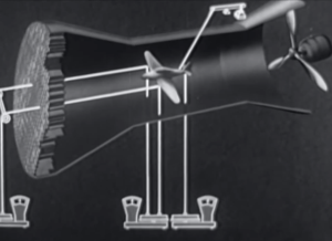
The forces that act upon an airfoil are measured in wind tunnels which provide straight and predictable airflow. A model airplane is supported by wires that lead to scales. These scales measure drag as well as front and rear lift.
In experimenting with angles of attack, lift and drag increase toward what is known as the stalling angle. After this point, lift decreases abruptly, and drag takes over. Lift and drag are proportional to the area of the wing, the relative wind velocity squared, and the air density. When a plane is in the air, drag is a retarding force that equals the thrust of the craft, or the propelling force.
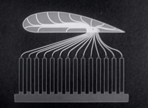 Airfoil models are also unit tested in wind tunnels. They are built with small tubes running along many points of the foil that sit just under the surface. The tubes leave the model at a single point and are connected to a bank of manometer tubes. These tubes compare the pressures acting on the airfoil model to the reference point of atmospheric pressure. The different liquid levels in the manometer tubes give clear proof of the pressure values along the airfoil. These levels are photographed and mapped to a pressure curve. Now, a diagram can be made to show the positive and negative pressures relative to the angle of attack.
In closing, we are shown the effects of a dive on lift as an aircraft approaches and reaches terminal velocity, and that lift is attained again by pulling slowly out of the dive. Remember that the next time you fly your hand-plane out the window.
Continue reading “Retrotechtacular: Forces Acting On An Airfoil”


