 Many people who use water cooling in their computer systems like to go full-bore with ‘aquarium’ aesthetic, which includes adding a window to their cooling blocks so that they see the water flowing through the window from behind the case’s window. Traditionally PMMA acrylic is used for these windows, as it’s quite durable and easy to handle.
Using glass offers some advantages over acrylic, but has its own disadvantages, most of all that it’s hard to process, but also that it’s known for shattering quite easily if pushed beyond its limits.
This is why [der8auer] as a manufacturer of such water blocks has now spent a few years investigating the viability of using glass for this purpose. First and foremost is safety, with an early prototype glass water block suddenly shattering without clear cause.
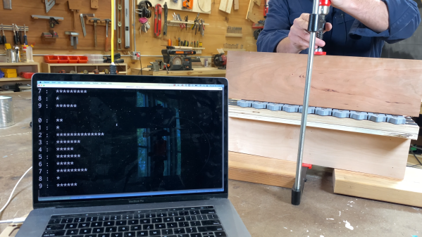
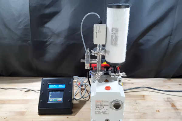
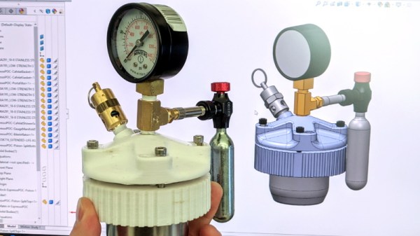
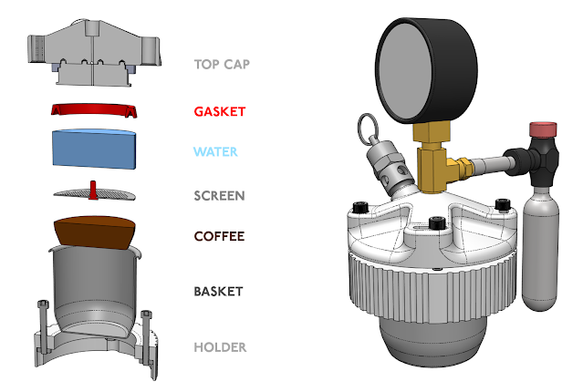
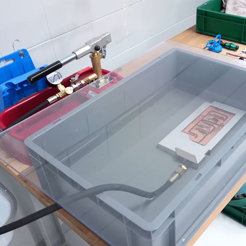
Although normally the water cooling loop is only expected to experience pressures of about 600 mbar, the new glass windows that are now entering mass-production had to be tested to their breaking point. This involves pumping water into a few test blocks until they fail, using the test rig that you can see above.
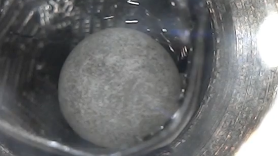
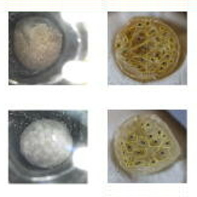
First the big GPU water block was tested, with the acrylic version breaking at around 8-9 bar, while the glass plate shattered at around 5 bar. The failure mode was also interesting, with the glass plate shattering into fragments, while the two acrylic plates tested failed in a completely different location and manner.
A smaller water block with glass window failed at about 10 bar, demonstrating mostly that smaller glass windows are a lot sturdier. Effectively glass windows in water cooling loops are viable, and they also do not suffer from e.g. discoloration, but you do give up a big chunk of your safety margin if your water cooling loop suffers a major pressurization event. Which of course should never happen, but we’re definitely looking forward to the upcoming field trials of these new water blocks.
Continue reading “Testing The Pressure Limits For Glass In Water Cooling Blocks”