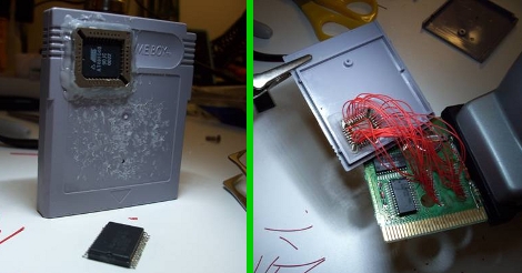
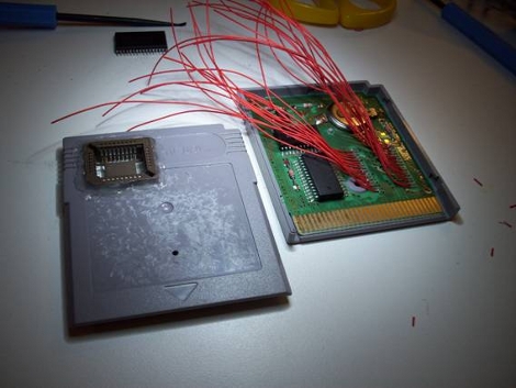
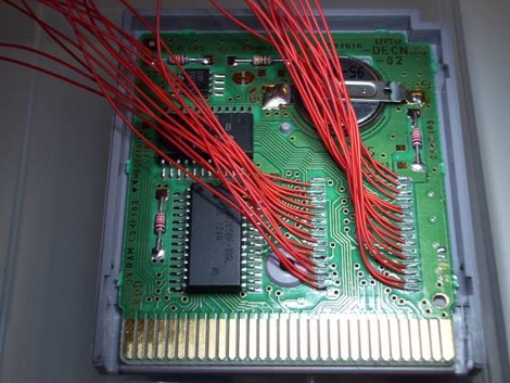
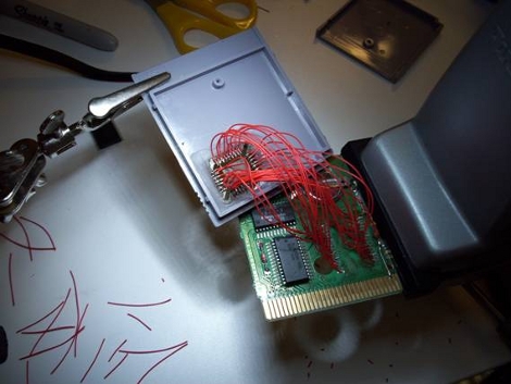
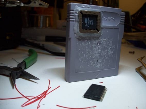
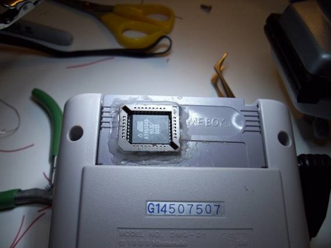
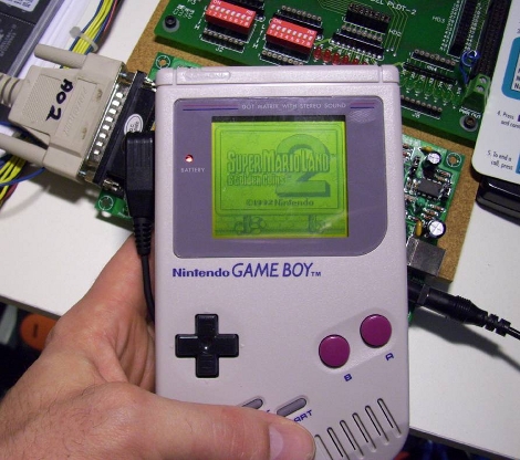
[Gerry] sent us pictures and a few details on replacing the Game Boy cartridge chip with a flash chip. For the prototype he used a PLCC and a little wire porn to interface a flash chip with the cartridge’s PCB while still having access to it for programming. In retrospect he plans to use a 32-pin ZIF socket on the next version to make things easier. It does work and he’s had some success loading his own code and getting it to run. There are other cartridge hacks that let you load code onto a cartridge but if you have the knowhow and the parts this makes for a fun weekend project. We’ve posted the rest of the photos that [Gerry] sent us after the break.
Update: Gerry is working on a video and a pinout. We’ll post info once we get a hold of it.




These are always the coolest mods. Very nostalgic.
That’s one helluva wiring job, kudos for that alone!
I recently stumbled upon my old Game Boy and have been dying to learn more about interfacing with the ROM. Over the past few months I have been studying as many cartridge mods as possible to try and learn more! This is SUCH a cool project, thanks so much for posting it!
I would love to see much more on this subject! I’m very interested in doing this myself and have been looking into it.
Sorry, when I look at that wire mess, the words “fun weekend project” don’t cross my mind.
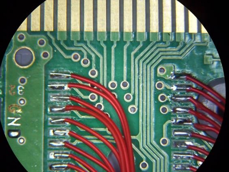
That’s some darned nice soldering right there!
Thats a very Oldskool way of hacking ur old Gameboy, Im going to add some more IO. There are more projects like these on http://www.reinerziegler.de/readplus.htm
and some here
http://www.devrs.com/gb/.
Keep those GB hacks comming!
Classic hack. I’ve done this a decade ago or so, but with a DIP40-chip instead of a PLCC-one and with wires sticking out of the back. This looks much nicer!
Love it.
I hope this can be done for the color as well. I still have my GBC, and would love to flash all my roms to one cart.
Home made flash carts have been done many, many times but I must admit it doesn’t make this one any less impressive. However, if I’m not mistaken, that’s an MBC1 cartridge… I don’t understand why he wouldn’t just do this with an MBC5 cart instead and get the extra functionality and compatibility. Unless this was all he had lying around of course.
Anyway, good work. Hoping to see more Game Boy-related stuff on Hackaday in the near future.
now this is a hack., keep em comming./
Awesome! I wonder if it will work with the RetroVision.
http://nintendoage.com/forum/messageview.cfm?StartRow=1&catid=6&threadid=32896
Some cartridges use the correct form-factor already I think. Saves some wiring.
You just can’t choose the bank controller, but this isn’t for pirating anyways. right?
For coolness, wires are ok though.
Wow. That’s a lot of hand wiring. When I’m faced with that much wiring, I usually end up doing an ExpressPCB board…far neater and way more reliable.
From what I can tell, a lot of people here don’t even TRY to do a half decent wiring job. man, what a mess. What’s worse, is people here seem to think “that’s great man!”
It really doesn’t take that much more effort, that’s one reason I’m so surprised to see this sort of thing.
And you don’t need a ZIF socket, just use a chip puller on the one you already have.
@George Johnson
Or buy one of the chinese flash carts that support all the different mappers (or at least patch roms)…
@All
I’ve done this with a GB cart.. I’ve done this with a NeoGeo MVS cart too. You soon get pissed off with pulling EPROMS, progging it, putting it back in the cart, seeing that it doesn’t work, change code, pull rom,.. For GB/GBA/DS work the nocash emu/debuggers are the way to go until you really need to test on real hardware.
@Asuraku
You can’t flash all your games to a cart with only one MBC type/a small EPROM. You can get chinese GB/GBC flash carts with usb these days.. google is your friend.
I gotta say that I pretty much LOVE this kind of soldering job.
If only I could teach my hand to be steady enough to solder like that.
@Matthew
You don’t need a steady hand to solder like that.
You don’t need a fine soldering tip either.
A decent iron with a medium size tip and a rosin flux pen is all you need for a job like that, maybe a jewelers loupe to check your work. The key is to let the flux, pads and solder mask do the work for you..
It’s perfectly possible to solder TQFP100 and similar packages by hand with a cheap iron if you think about what you’re doing.
@ cantido
Thanks for the pointers.
If only I could buy flux locally.
Acid, acid, acid.. that’s all anybody has.
Radio Shack (I guess they’re “The Source” now) doesn’t even sell the stuff. The salesman there told me that “all our solders have flux built in”… He even seemed proud.
Talked about soldering daily or something. I doubt the guy ever lifted an iron to do anything aside from re-solder a broken battery contact!
Would it be possible to connect up, say, an arduino rather than a flash chip and generate the code on the fly? GB and GBC use original z80s I think, so it should be possible, but the timing could be a bitch and you’d need to write pretty tight code to guarantee that you don’t screw it up.
OMG I did this exact same hack a few years ago, I even build a cartridge burner, so I wouldn’t have to swap chips – cause it was a PITA, I ended up with my PLCC socket was actually flush with the cart case, right above the rom area… I never managed to get it to burn right, and eventually took it apart and replaced the original Metroid II rom back in – (it still worked :P to my delight!)
@ENKI-[] – IT IS possible to do what you ask, BUT you’d have to poll in 16 address bits and the r/w lines and access whatever memory you have attached to the arduino, the arduino is a 16mhz device, and the GB is 4mhz – there just aren’t enough clock cycles to get it in under the wire (pun intended) – as in before the gameboy would expect it to be there. – look into FPGA rom emulators, I’ve seen lots of projects out there for them, if you’re still interested
Hi Folks,
Glad you are all liking the Hack I completed.
Except for my Messy Wiring work. :)
In Response to George Johnson’s Comment:
“And you don’t need a ZIF socket, just use a chip puller on the one you already have.”
That was actually my intention with this design. However, the reason I mentioned using a ZIF socket as opposed to the PLCC; was due to the amount of wear and tear that was occurring with the PLCC socket. PLCC sockets were usually used for BIOS chips and are only meant for periodic changes. Now in contrast, the number of times a user will be re-programming their flash chip when trying different games is much higher. This is the same reason why Universal Programmers are equipped with ZIF sockets.
Or shall I say “Zero Insertion Force” sockets.
To me it just makes the chip change and re-programming much faster overall.
But Hey! That’s just me. :)
hi,so it works?i mean,u replace the chip,which contains the game,right?and u put a flash drive and reconnect the wires and it works?u can play any game u want ?
Go to the Gameboy_Electronics Forum if you need some help getting your Gameboy projects up and running.
It’s there if need be.
http://groups.yahoo.com/group/GAMEBOY_Electronics/join
Tom