[Ken] needed to supply 3.3 volts of regulated power. He started by using a linear voltage regulator but after a few calculations he discovered that 72% of what he put in was lost to heat. The solution to this is a switched-mode power supply. Rather than burn off energy through a voltage divider, an SMPS turns the power on and off very quickly to achieve the desired voltage.
A car charger-type USB regulator was chosen as [Ken’s] donor device. He figured that making adjustments to the resistors inside would affect the output voltage and he was right. He adjusted the potential divider and ended up with a steady 3.295V.
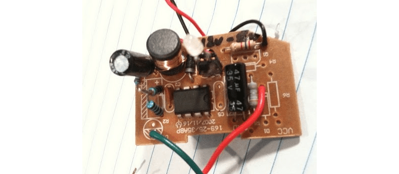
We asked him to share the schematic that he put together from studying the board and he came through. See that and get the link to the DC-DC converter datasheet after the break.

Above is [Ken’s] hand drawn schematic. After conversing with him about this project he grabbed a jeweler’s loupe and was able to identify the DC-DC converter in the circuit. It’s an MC34063 whose datasheet can be found here (PDF).


This is a great article and I appreciate the inclusion of the datasheet.
cool. i didn’t know changing the resistors changed the voltage. i thought it was the chip.
Potential divider is usually described as voltage divider. Not saying that it would be incorrect but using potential divider is just not as common so I thought I will mention it for clarity :)
The theory itself: http://en.wikipedia.org/wiki/Voltage_divider
Switching power supplies are nice, but they can have awful harmonics and produce a “hum” on the output. If you need a clean signal, make sure you filter the living daylights out of the output.
@Chris
It is the chip. However, the IC regulates to a setpoint (normally in the 0.5 – 1.0V range). Normally you use a voltage divider on the output to feed back the output voltage.
I don’t know why hobbyists are so afraid of DC-DC converters. A lot of the recent (2000+) chips make it extremely easy. The datasheets are very well documented and include example circuits and all the equations you could ever want. Very few modern chips have any sort of loop compensation issues to worry about, meaning they work with virtually any inductor and capacitor. Seriously, don’t be afraid of these circuits, go try it!
@charper: I can’t speak for everyone else but in my case it’s a couple of factors that come into play. They sound complicated and when you look at the datasheet there’s a whole slew of different circuits drawn up and a whole bunch of “support circuitry” (which also adds to the footprint).
An LM78XX or similar device is simple, drop it in with a couple of caps, done. This speaks to the lazy side in me.
And cost, the switched mode route is much more expensive as far as I’ve been able to tell (IIRC the last time I checked for a project it was something like a $1 vs $10 relationship).
I would absolutely love to be proven wrong in my rather poorly educated assumptions though.
Switched power supplies can also throw noise into the circuit.
I would say inductors are the reason why I don’t use them. I really hate making inductors and I don’t have many pre-made inductors marked with their values lying around.
I do like the idea of modifying a car DC-DC converter. They are relatively common, so it wouldn’t be difficult to tweak one and put it into a DIY project.
@sneakypoo
Yeah, your assumptions are (unfortunately) more or less correct.
@Nicko01
Yeah, agreed 100%. It’s also really hard to find inductors properly spec’d out in a datasheet. Fine, you know the inductance, and the max current. But that’s usually the max current due to ohmic heating, and not core saturation which tends to happen first. Likewise, for flyback converters B-H curves are rarely given. That part is a real PITA.
Although, one partial solution to both of your qualms:
Look up Coiltronics’ “Versa-Pac” inductors/transformers. They’re coupled inductors normally in the $5-10 range and the datasheet is decent. The really nice part is they can be used as both inductors and transformers, and different arrangements give you some flexibility in prototyping. They’re still pretty bad for flyback though, so you’ll have to stick with the standard buck/boost topologies. Isolated you’re limited to forward.
I have to agree with sneakypoo also. I”d love to see 78XX’s come from 01 to at least 48. I don’t have a need for anything higher than 24VDC myself, but I won’t speak for the rest of the world.
I have run into a device called an Anyvolt.
http://www.dimensionengineering.com/AnyVoltMicro.htm
But I can’t justify the cost except in a prototype.
I just use MCP1701 ldo’s.
Sometimes in my filter circuits I use gyrators in place of inductors, you think that would work in this case?
http://en.wikipedia.org/wiki/Gyrator
Have a look at LTSpice to simulate your own DC-DC converter.
I share the qualms of using them, but they are much more efficient than wasting the excess energy via a coolant device, which is often simply too big for small designs in case you wan´t to do it right.
wbr,
ab
It’s a bit iffy to just go changing the voltage set-point in a switcher without a good understanding of the component values and parameters involved. You can end up saturating the inductor, which tends to make things hot (and stop working, with smoke).
If you want to design with switching power converters and you don’t want to use the off-the-shelf modular solutions, you should read this book: http://www.amazon.com/Switching-Power-Supplies-Sanjaya-Maniktala/dp/0750679700/ .
The first few chapters are pretty straightforward, and they give a good idea of the calculations you’ll need and why they work.
I have a fondness for charge-pump regulators, esp the MCP1253 from Microchip. They don’t use inductors, the circuits are really simple, they are more efficient than linear regulators, and can boost lower voltages to what you need (e.g. use two AA’s for 3.0V to power a 5.0V circuit).
<3 Microchip
The issue with charge pumps is that maximum current is very, very low. Most charge pumps I see are 69-75% efficient and can supply up to 50ma, which is fine for a microcontroller, but can cause trouble if the project uses say, a white led backlit display and you are powering it from 3V.
@daniel
Agreed. However, looking at the calculations in the datasheet (after the fact), you can calculate the minimum inductor value. Even without known values for some of the parts, you can see that the relationship between output voltage and minimum inductor value are linear. A drop from 5V to 3.3V is unlikely to cause catastrophic failure and is a small move in the right direction for the existing inductor (220uH, IIRC).
Now, trying to pull 9 volts or 2 amps out of this circuit that’s likely designed for 5V @ 500mA(max) could let the magic smoke out; I will certainly concede to you on that.
Note that this project is only worth it if you have one of these laying around. I wouldn’t go spend $20 on a car charger just to get the SMPS out of it. There are certainly better ways of doing this.
I too found the process of building my own switching power supply a bit daunting and was also considering modifications to an existing unit. I was eying a USB car adapter from Deal Extreme (SKU 40470). Its regulating chip is the XL1509 which seems to be versatile.
Is there a place to buy assembled switching power supplies of various output and input ranges for a decent price? Or am I better off just modifying and or building all of my own switching power supplies?
I’ve done this dozens of times over the last 10 years. Just look at the spec sheet for the controller, and it will usually have a chart that shows appropriate inductor values for given output voltages. Changing the output voltage by less than 50 percent usually doesn’t require a change in inductor value.
@Bronze3G:
Thanks for the tip!
@Bosnoff:
DC-DC converters are quite common, and lately, are not that expensive. Particularly, check out “Point of Load” converters that tend to be quite cost effective if you don’t want to bother with building your own buck converter from scratch…
I should add that one of my favorite uses for this hack is for Power Over Ethernet applications. I use a power inserter supplying 18 Volts(considering line losses will drop the voltage a few volts over long distances) to power a standard cigarette lighter adapter modified to supply the proper regulated voltage to the networking device at termination. RJ-45 pins 4 and 5 for positive, and pins 7 and 8 for negative… :)
@daniel
Thanks for advising the book, I was looking for great read
Here’s a design tool for the MC34063 that computes for all the values needed for your application. Use the datasheet as a guide for the fmin and vripple values.
http://www.nomad.ee/micros/mc34063a/index.shtml
I would say 4 out of 5 cigarette lighter power supplies ive opened are made of this IC because its super cheap!
Great stuff!
I recently used a couple of car-type switching converters in projects of my own.
In one project I replaced a linear unit that generated alarmingly wasteful amounts of heat and the switcher did the trick!
@royco, I was about to post this link till I found you had done that already! good stuff!
I use the same type of circuit, but instead of a a fixed value for R3, I use a 2k precision 10-20turn pot to get the value(3.3v) “dead on”.
While the efficiency of switching regulators can be quite good, the transient response of switching regulators is usually not anything to be proud of, especially with an impulse or step response. Such is the price of things obeying the law of “you can’t get something for nothing” Depending on the circuit and the type of low-pass filter on the output there can be some serious overshoot/undershoot, ringing, and delay before the voltage settles to the correct value, which is why switching regulators are usually pretty bad for hifi audio. A good way to test the response of a supply is to get a simple FET or BJT, drive the gate/base with a square wave, and have a low value resistor in series between the supply output to be tested and the collector/drain. Watch the supply voltage on a scope, you will see what I mean about ringing and overshoot/undershoot.
If your application can tolerate this, there is no problem.
^Big CAPS! :)
I’ve gotten a couple modular SMPSes from Texas Instruments. They can source more current than their 78xx brethren.
http://focus.ti.com/docs/prod/folders/print/pth08080w.html
If you sign up for free, you’re eligible for their sample program. And it’s really free, not even shipping.
i have constructed the circuit and its perfect but am having problems with it charging a blackberry phone i need help on this pls if there is any one that can help