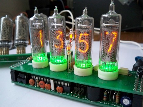
The Warm Tube Clock is the new kid on the block of Nixie Tube clocks. It takes inspiration from, and uses the same voltage driver circuit as the Ice Tube Clock. But this one uses four tubes instead of that hard-to-find single tube. It has a few other tricks up its sleeve. The shield that hosts the tubes has been designed for two different types. It also hosts an RGB LED for each tube, which adds the green glow seen above, and has a couple of small neon indicator bulbs which serve as the colon between hours and minutes.
The driver board centers around an ATmega328 running about three thousand lines of code. The firmware offers a lot of options including sound feedback, and a setting for every clock, calendar, alarm, and LED color toggle imaginable. See for yourself as the settings video, embedded after the break, walks you through each stage of the menu. We can’t help but think you need an instruction manual to set this thing up.
[youtube=http://www.youtube.com/watch?v=szHUmyoqAvA&w=470]
[Thanks Mark]


Nice idea with the RGB LEDs…
Good “UI design” :)
I will definitely be getting some of these PCBs made. Anyone want to split the cost with me? The house I use is $40 for 10 boards
Hmm… How about something like this that acts as a physical Gmail or Email notifier?
@bill email me, id def like to get one of the pcbs made up to clone this project.
nutz4hs(@)yahoo(.)com
Will do, and anyone else, I’ll save you from posting your email address here. Just shoot me an email at clockpcb(at)billporter(.)info
Since this is really two boards, it will be $80 for 10 ‘sets’ of PCBs. Or $8 per person if we get 10 people in on the pool.
@Author of project
You should take at least one picture without flash, the LED’s look like a cheap addition without some proper photographs.
Otherwise a cool project. I use the IV-18 VFD tubes, don’t think they’re too hard to find…
Do you guys know of much current such a clock would draw?
@Paul
It helps to read the website.
“Clock works at voltages from 7.5V to about 14V and consumes around 200mA. “
Very cool! I have one Nixie tube clock that I bought as a kit and built and I love it. I like the additional features in this clock (alarm) and would definitely be interested in one. But the PCB’s definitely need to have some sort of mounting holes/standoffs on them. I don’t see how this particular board can be mounted in anything.
Want kit!
@Spork: hey, there is a picture without LEDs: http://bit.ly/ec1ACz and many more pictures.
I am glad you guys like the clock :-)
@elektrophreak,
Love it, saves me from having to design my own. Though I would have liked to see seconds as well.
@Tom
I agree, I’ll try to add mounting holes.
Don’t forget to email me guys if you want to get in on a group order of the PCBs.
if mounted in an acrylic box, one hole is enough – the one through 7805 regulator, with plastic standoffs.
there are some PCBs available – check the project page if you are in a hurry to build one :)
What? I didn’t see that on the project page.
Ahhh, you’ve added a update to it. I’ll copypasta it hear as well.
“UPDATE 2: I have received a few e-mails regarding the KIT version of this clock. In order to prepare all that, some investment is expected from me. To give that a boost and to help all of you who want to build a clock right now, I have some leftover PCBs and you can purchase all three for the entire project (main board + IN-16 shield + IN-8 shield) from me directly. If you are interested in PCBs, just send an e-mail to: kit at elektronika.ba with subject: “warmtube pcb” or “warmtube kit” if you think you will ever be interested in a KIT version.”
What is the price your asking for the 3 PCBs?
Hard to find IV-18? eBay has a bunch, link below if anyone wants to buy any.
http://shop.ebay.com/?_from=R40&_trksid=p3984.m570.l1313&_nkw=IV-18+Tube&_sacat=See-All-Categories
Anyone know where I can find documentation of firmware? Ide like to build about 6 of these and hand them out as gifts with a “User Manual” of some sort. :)
You can download everything on the project page.
I am currently making a build (soldering) instructions with pictures that will be used as a “users manual” during assembly.
Great design only problem it is a 24 hour format. Do you intend to do a 12 hour version or option for us bloaks in the U.S.? I think one of the colons could be a PM indicator and the code would have to be modified slightly. I would be willing to help monetarily for the information if necessary. Thanks….
Hi! An interesting project. I need help from the author. I made this scheme,V1, but not everything works. Leds are flashing green lamp always shows 44: XX (xx is all light instead of numbers), then changed to XX: 1, and nothing changes when you press the button. Maybe there’s another firmware? Give me please.Thanks!