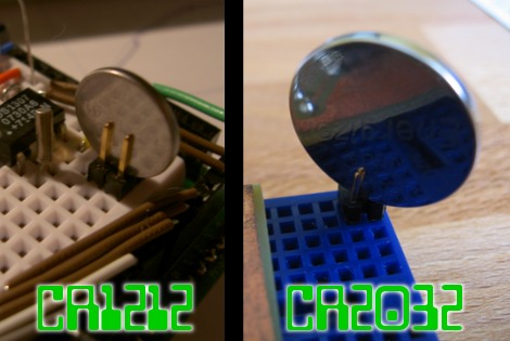
We’re working on a project that has a battery backup, but we don’t have any more coin cell holders on hand. No problem, we remember seeing a double pin header used for this. But when we tried to shove the CR2032 battery in between the pins it was a no-go. We could swear we’d featured a project that does this but couldn’t find it here at Hackaday. After much searching we came up with the Guerrilla battery holder which is seen on the left. No wonder it wasn’t working, the CR1212 in that picture is a much smaller package. So we figured we’d have to come up with something else, until inspiration struck.
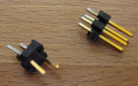
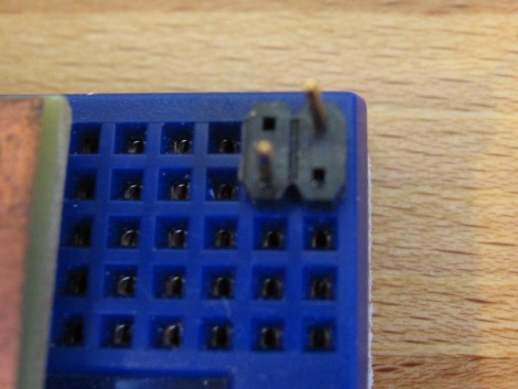
There must be some other way to configure the pin header to work with a fatter cell body. On the right you can see that a diagonal orientation works like a charm. Join us after the break for a couple of close-ups of that connector and our thoughts on using this with a variety of different cells.


To make this connector two pins were removed from the 2×2 pin header, leaving room for the CR2032 battery to fit nicely on an angle. We also centered the remaining two pins in the plastic body to make enough of a tail to seat well in the breadboard. Now that we’ve done this, it should be simple to make it work with any coin cell. A bit fatter package might work with the center two pins removed from a 2×3 header, or on an angle with just two diagonally oriented pins on a 2×3 header. Give it a try with your battery of choice. It might just get you through the prototyping phase until it’s time to put in another parts order.


Simple and genius.
This is really great! Nice tip.
Is that an arduino I see there?
Not an Arduino, it’s a DS1307 real-time clock
@Simon Inns – anyone could google the part number. Amishx64 meant underneath the breadboard in the first Picture. It looks like pcb board and i doubt its an arduino. aren’t those usually blue?
Wow you guys actually posted a “hack” on how to turn a battery. :S
wow , the simplicity is just beautiful
I’m surprised this isn’t standard practice. Seems like a prefect answer. thanks for the heads up
hey, you can also us a 3,3V or 5V Power CAP like this: http://www.we-shop.eu/passive-Bauelemente/Kondensatoren/Gold-Cap/ELNA-Gold-Cap-Speicherkondensator-1-0F-5-5V::4707.html
OMG WTF and other memery!!
Never thought of that and now i am ashamed.
Awesome.
This solution is so simple, yet so awesome.
Good job!
Nice. I’m currently working on a project which I want to place in a VERY small enclosure, small enough that a coin cell will barely fit, sideways, in a lidded cylindrical container. This idea should make things a little easier, I’ll just need to secure it a little better.
You mean you don’t just solder wires directly to it?
solder wires/ wire-glue if that crap works.. to neodymium or any other conductive magnets of appropriate size. hard drive magnet for the base, smaller one for the other terminal. a little soldering isn’t going to hurt your magnet’s strength that much, and really, you could just use the magnets (insulated to prevent shorts) to clamp your connectors to the battery, in which case i would probably solder some appropriately sized washers to wires, one hard drive magnet should be more than enough for the task.
for the vertical breadboarding arrangement, big metal backplate where the 2 pins are shown, and on the other side a wire held in place by a small magnet. another magnet on the back would offer extra security, but depending on the strength of the one magnet, may be overklll
why not just take a 2×3 and remove the center two pins and bend the ends in to allow for a larger battery size? If you do this with pliers you will not break the plastic.
By the way, in case anyone isn’t aware, the size of the battery is in the number (1212, 2032, etc.).
CR1212 is 12mm wide by 1.2mm thick
CR2032 is 20mm wide by 3.2mm thick
etc.
I used a similar method for an SD card holder. I saw the idea on Instructables (might have been posted here too some time ago). Three pin header pieces soldered in a Y shape with the pins bent to press against the pads on the card and I had a working, reliable connection to my SD card.
And CR relates to the battery’s chemistry, if I heard correctly.
I’ve never been able to solder directly to coin cells even with a rather aggressive flux. perhaps I just need a higher power/temperature iron.
I was even going to go so far as to etch some PCB stock and cut it into 3-4 pieces:
1 piece as the positive side (copperclad)
1 piece as the negative side (copperclad)
1-2 pieces as plain laminate spacers (1.6mm boards, double stacked for a 2032.
Small, custom battery compartment small enough to fit almost anywhere. Just solder pins or wires to the copperclad end pieces.
Ha, good idea! So simple.
Silver soldr works great on coin cells. I solder on my own leads all the time.
You can just put bare wire against the battery and then wrap electrical tape around to keep it connected. The BIOS battery back up in my old laptop worked like that for about 5 years.
@fartface:
Silver solder?! How do you do it? Anything I silver solder, I have to get it dull red (about 625 deg. C or 1150 deg. F) before the solder will stick. I wouldn’t try doing that to a battery. Please explain?
@gyro_john
Silver solder also refers to silver/tin alloys that come in spools like lead solder. It melts around 200*C rather than 600*C of silver solder rods used in plumbing. I’m guessing that’s what he means… or it’s a joke.
I feel like I should have thought of this lol…so simple but seems to work so well…and for such a common problem…great idea
Riggig a miniture wooden or plastic clothes-pin is pretty secure. It works well enough for projects that a meant to be on the move.
If you need a real dependable solution I would either salvage a component from an old motherboard of buy a bicycle led coin battery light and use the housing from that. Just remove the light and rig the PCB so 2 wires come from the housing.
The options are rather endless.
@ Dosbomber
I did not know that. And now I do. Thanks!
Not a good idea to solder these batteries as you will ruin them or severely reduce their capacity.
If you MUST have a permanent connection, look into spot welding like they do on Li-ion cells.
@alan could be a protoshield for the arduino :)
@jeditalian
Thanks for the battery idea, I need to get some batteries into my watch somehow. I’ve got some little 1 mm neodymium cubes, just the ticket!
Excellent tip! Good to see that one can find everything from simple application of pin headers in non-standard way to building your own silicone transistor from scratch.
not all cr2032’s have a high iron content in the shell. usually they stick well but i’ve got one from a motherboard that barely sticks to neodymium
That’s true innovation, grat stuff!
could you use a pair of insulated wires to retain it by wrapping around the top of the coin cell and pulling through the board to make it mostly shock-proof?