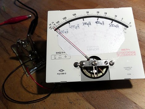
[Apexys] is performing some experiments with switched-mode power supplies and needed to compare the inductance of the coils he was using. His multimeter doesn’t have an inductance testing function, but he does have a 555 timer on hand. He put the 555 and some other parts together to create his own L meter. The writeup includes the theory behind this meter, with an incoming AC source converted to a voltage by an RC network.
Once he’d worked out the design it was time to build the circuit. Instead of printing a circuit board he created what he calls a DCB; Drawn Circuit Board. We’ve got to admit that this was way faster than using toner transfer or soldering point-to-point. We also like his use of an Erlenmeyer flask and a torch to heat the etchant. We don’t make PCBs in the winter because our Cupric Chloride is too cold to use outside but that may change now. The final piece in the puzzle is an analog meter which he pulled from an extra microamp meter he had on hand. Check out the demo after the break.
[youtube=http://www.youtube.com/watch?v=PxVmkd5yD6Q&w=470]


um, this is awesome. well done.
This is UBER! Absolutely the bestt 555 project i have seen yet!
Well Done!
Very clever. I remember reading about using the venerable 555 for capacitance measurement. The “DCB” is a definite takeaway. Nicely done and having access to the simulation files are handy too.
Wouldn’t this produce false readings if you were to measure a resistor instead of an inductor? Or an inductor with a large DC resistance?
From what I figure, the meter is pretty much reading the average voltage on the oscillating tank circuit. Larger oscillations means higher average. Since you’re not oscillating at the resonance of the tank, you’re approaching the resonant frequency 1/(2*pi*sqrt(L*C)) from the lower end. So a larger inductor will produce a lower resonant frequency which will be closer to the 555 frequency and thus you’ll have larger oscillations.
If the meter reads the average voltage, then the inductor can be replaced with a resistor and C2 will charge and the resistor will slowly discharge it during the off cycle. You’ll still get some level of “oscillation” showing up to the meter and therefore it’ll still read some average level.
555s and Erlenmeyer flasks for the win
I cannot see any feedback in this circuit! So oscillation frequency is independent of inductance value. Measured current has some dependence of inductance, but a bit more sophisticated than it would be desired. Circuit is peace of sheet, author is asshole.
Absolute garbage circuit. Tried numerous inductors and nothing changed. eveyrone stayed exactly at same level. Dont waster YR time.