A little while back I attended the largest east coast gathering of folks from the ever popular social news site, Reddit.com. Those of you familiar with Reddit already know that it is all about link aggregation. Users post links to interesting websites and material, and can then vote up or vote down content based on interest or relevance. Through the magical site algorithms original and interesting content is, as implied, aggregated up to the front page. The whimsical nature of this big DC event lead many people to furnish signs of all types based on the culture of the site, internet memes, etc… The signs that really caught my attention were based primarily on the stylistic site layout, blowing up mail icons and other Reddit specific graphics.
The concept of using site graphics gave me the idea of being able to personally vote up or down other peoples’ signs. It was far too easy to just make a cardboard arrow, and I don’t have a color printer. I happened to have a shelved coffee table project involving orange and blue LEDs. Same colors as the arrows! Sweet. To make this project work I would have to work entirely from my project pile, there simply was no time to order anything from the internet. I managed to crank out a functional up/down voting sign in 3 days leading up to the gathering (and the morning of), here is what I did:
What I Had Around The House:
- Orange and Blue LEDs – 124 each. Extras from a coffee table project that is currently shelved.
- Breadboard – I have tons of this stuff lying around, surface mount friendly square flavor!
- MOSFETs – Another shelved project, an electric motor controller so these could handle many amps.
- Resistors – I only had SMD resistors in the values I needed, this turned out to be a huge hassle.
- Arduino Nano – I keep this one kicking around project free for just such an occasion.
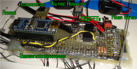
- Trippe Axis I2C Accelerometer – I built a little breakout board and toaster oven soldered the thing a long long time ago. We only really need one of the three axises for this project.
- SPDT Switch.
- Voltage Regulator – The Arduino could technically make enough 5v to power everything, I decided to not risk it though.
- A knife worthy of foam core board, I used a pen knife.
- Tweezers, solder, soldering iron, wire, a steady hand, patience.
Stuff I had to get:
- Poster Board – Craft store!
- Hot Glue – Craft store!
- 9V battery clips – This was a snap decision, I got these the day of the event!
Layout The LEDs:
Now its time to recreate the pixel graphics. The site has a very simple low res graphics, below is a close up of the activated voting buttons.

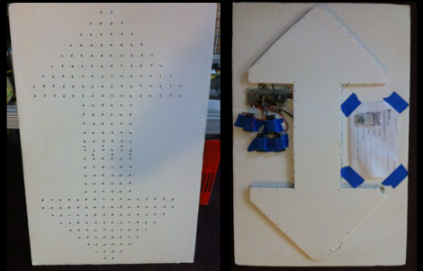
Since I have far more LEDs than sense, I decided to place an LED at the intersections of the pixels. All these great ideas on how to diffuse the light were tossed around, wax paper and what not, they would have looked amazing but time intervened. I had to pick a strategy and go with it. I traced the pixel art onto peg board and used the holes as a guide, the total is 124 LEDs per arrow. In order to fit in one inch squares the arrows overlap one another. The design was drawn out onto peg board (again the coffee table project) and then transferred to some foam core poster board.

This left a nice guide for all the LEDs. There are companies out there that make very specific foam board hole punches, but my local craft store had nothing like it. So I was forced to use the pen knife to spoon drill the holes, all 248.
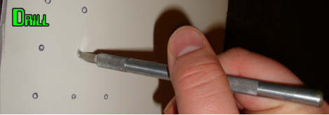
Once all the holes were drilled I had to press the LED into its slot, this was pretty labor intensive. 5mm LEDs can really damage your fingers.

I tried to get the arrow gradient by spacing out the last couple LEDs in the pattern, it went okay. Some resistor tweaking could produce a more convincing fade out. Dual orange/blue LEDs would have been even cooler. To protect all the wiring and LEDs I glued an arrow shaped section of foam core to the back of the sign (left over from diffusion experiments), this let a bit too much light through the back of the edge LEDs. I’d recommended cutting a slightly larger backing and attaching it with a weak adhesive or Velcro to allow future access to the electronics.
The Circuit:
Now that all of the LEDs are mounted I plugged a few variables about my setup into an LED calculator. I had to determine some values experimentally since blue and orange are slightly different, and I long since have lost any data pertaining to them. My source voltage is 18v, I used a multimeter to find the voltage drop and a power supply with a current meter to measure the forward current of the LEDs.
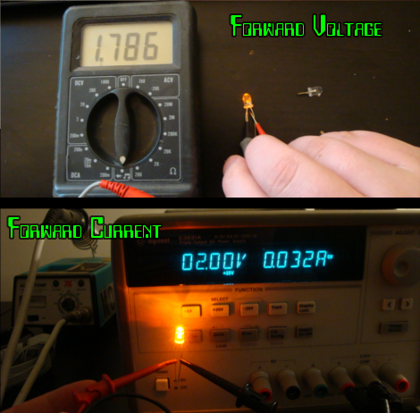
The calculator told me I could string the oranges up in chains of 9, with a 1Ω resistor for each chain. The orange array would draw 448mA from the batteries. The blues each consume 4 volts and around 70mA (!!). The blues were wired in groups of four, with a 33Ω resistor on each chain. The blue LEDs draw 2.1A from the source. This is about when I decided on the heavy duty MOSFETs from an electric motor project. The leads of the LEDs were then bent down to wire them together. Since I only had surface mount resistors I had to run ALL of the LED positive wires back to the PCB using some wire wrap wire I had lying around, this is one of those cases where a through hole resistor and some thick bus wire could have made life MUCH easier. The LED grounds were created with some low gauge bus wire, and separated for the up/down portions of the sign.

Switches are fun, people love a good SPDT. They are robust, can handle lots of current… they are really good at toggling LEDs. You know what people really love though? Accelerometers. People love accelerometers, and I happen to have a whole hand full of these buggers in my pile of goodies. Somewhere in the solder smoke and endless wire bonding I had the insane idea to use my spare Arduino to control the arrows, and trigger them off some sort of gesture.
Below is the final circuit. The 3 axis accelerometer is extreme overkill, Cheap analog accelerometers are easily found soldered and coded for and I would go with one of those were I to do this project again. I also failed to include a potentiometer and code to fade the LEDs via PWM. Don’t judge me, I ran out of time! You may also notice that the voltage regulator is more or less tacked on haphazardly, I had a really nice switching regulator but the stupid thing had the audacity to explode! The nerve! At least it didn’t happen during the event.
Code:
The accelerometer I had on hand is the LIS3LV02DQ, which was offered by sparkfun back in the stone age. I found my own block of code to modify but the site is currently down, you can find a slightly more complete example of the original here and the sparkfun page also has code, this made life really easy. All I had to do was figure out what axis was vertical and set up a threshold to flip on either MOSFET. Gravity affects the axis facing down, so its threshold had to be offset by 1024. I also think the accelerometer was upside down since I wound up at a smaller negative number than positive, either way messing around with the serial output on really helps to dial in the values.
Testing also revealed that I needed some kind of ‘lock out’ timer. When you flick the sign vertically acceleration peaks on one axis but then reverses on itself as you pull the sign back down. I used 1 second although this value could be shorter. Here is the code, don’t forget to check out [Troy]’s code for more heavily commented accelerometer stuff:
#include <Wire.h>

// TWI (I2C) sketch to communicate with the LIS3LV02DQ accelerometer

// Using the Wire library (created by Nicholas Zambetti)
// http://wiring.org.co/reference/libraries/Wire/index.html
// This Code is modified to toggle two digital outs based on
// A sudden acceleration upwards or downwards on the Y axis
// -Jesse Congdon

//Modified code from http://research.techkwondo.com/blog/julian/279
//Thanks Julian.

#define OUTX_L 0x28
#define OUTX_H 0x29
#define OUTY_L 0x2A
#define OUTY_H 0x2B
#define OUTZ_L 0x2C
#define OUTZ_H 0x2D

#define XAXIS 0
#define YAXIS 1
#define ZAXIS 2

int downvote = 5; //pins 3 and 5 can handle PWM too
int upvote = 3;
int ledtoggle = 0;

int upgesture = 1800;
int downgesture = -1200;
int lockout = 1000;
boolean lockouttoggle = false;

void setup() {
Wire.begin(); // join i2c bus (address optional for master)
Serial.begin( 9600 );

Wire.beginTransmission( 0x1D );
Wire.send( 0x20 ); // CTRL_REG1 ( 20h )

Wire.send( 0x87 ); // Device on, 40hz, normal mode, all axis’s enabled
Wire.endTransmission();

pinMode(downvote, OUTPUT);
pinMode(upvote, OUTPUT);
}

void loop() {

int val[3];
// transmit to device with address 0×1D
// according to the LIS3L* datasheet, the i2c address of is fixed
// at the factory at 0011101b (0×1D)

Wire.beginTransmission( 0x1D );

// set the MSB so we can do multiple reads, with the register address auto-incremented
Wire.send( OUTX_L | 0x80);
Wire.endTransmission();

// Now do a transfer reading six bytes from the LIS3L*
// This data will be the contents of the X Y and Z registers
Wire.requestFrom( 0x1D, 6 );

while ( Wire.available() < 6 ) {
delay( 5 );
}

// read the data
for ( int i = 0; i < 3; i++ ) {
// read low byte
byte low = Wire.receive();
// read the high byte
val[i] = ( Wire.receive() << 8 ) + low;
}

//keep this in for testing
//Serial.print( " y_val = " );
//Serial.println( val[YAXIS], DEC );

//Now that we have a Y value, does it signify a jerk up or down.
if(val[YAXIS] > upgesture){
ledtoggle = 1;
lockouttoggle = true;
}

if(val[YAXIS] < downgesture){
ledtoggle = 2;
lockouttoggle = true;
}

//blue? orange? what are you trying to say to me toggle.
switch(ledtoggle){
case 0:
digitalWrite(upvote, LOW);
digitalWrite(downvote,LOW);
break;
case 1:
digitalWrite(upvote,HIGH);
digitalWrite(downvote,LOW);
break;
case 2:
digitalWrite(upvote,LOW);
digitalWrite(downvote,HIGH);
break;
}

//This allows me to pause the program to avoid debounce
//also you dont have to throw the sign and gently catch it to
//make it change.
if(lockouttoggle == true){
delay( lockout );
lockouttoggle = false;
}
}
Results:
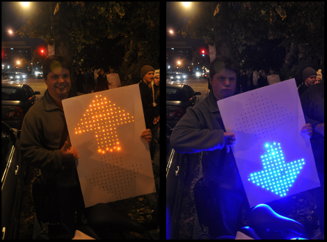
Sucess! The batteries ran down on me several times (I learned four packs of 9v batteries are expensive). My battery issues stem from the long chains of LEDs. You can see in the above image that the oranges are already starting to die while the higher current blues are destroying the camera. Also note that the remaining 7 LEDs got their own chain and are, as a result, much much brighter. Therefore, smaller chains of diodes means that the LEDs can stay bright under lower voltages. Silly of me to not realize this sooner. The orange LEDs would become tough to see after about an hour of continuous use.
This was a really fun project, everybody got a kick out of it and I think I have invented a new form of crowd control.
[youtube=http://www.youtube.com/watch?v=ptaiiarhj2Y&w=470]
Thanks for reading!


inb4redditcomments
Too bad reddit is currently in emergency mode.
PWM those LED to half brightness? That should reduce the power a lot and can be done without extra parts.
But I think the lesson here is that for some things LED are NOT the answer, or at least not with 9volt batteries, use a small-ish 12V bike battery or something.
@Whatnot I actually intended to go with a cordless drill battery, but I needed something that could be bought at shops (in case it died) and something light to mount on the sign itself. I wasn’t about to wander around huge crowds in DC with electronics wired into my bag. 9Vs can be found at 24 hour drug stores too.
AA cells can also be easily found, and have much better capacity and maximum current draw for this type of thing.
@jesse Yeah the availability is good, but still heh, those 9v only hold a very tiny amount of mA.
From 300mAh for NiMH through 400mAh for old style carbon-zinc through 550mAh for alkaline to 1200 for lithium, but that’s gotta be pricey.
And with that many LED, ouch.
Might even be better to use a CCFL in terms of poweruse, which I think draw about 500mA per tube?
I actually don’t recall ever seeing an arduino controlling a CCFL come to think of it, not that I’ve seen every project of course :)
reddit is the shit. For those of you who haven’t visited, give it a shot. Hopefully it’s not currently down. I guarantee you that when it’s up, it’s a site worth bookmarking if not homepaging.
@gdogg Reddit’s crowd are a bit of a weird cult though, and it’s not for everybody, but sure it’s not a bad idea to check it out to see if it’s for you.
Another way to go for this would have been to use a fiber optics bundle instead of discrete LEDs, ala http://www.instructables.com/id/Star-Map/. Still, great project.
try multiplexing the leds for the power consumption issue. :)
Nice :) What MOSFET did you use?
Great question, let me pull up a few order histories and see if I can find it! It is way way overpowered for this application though, it was really meant for an electric motor.
Here we are, it is the IRF 3205 Power MOSFET 55V 110A.
reed switches….