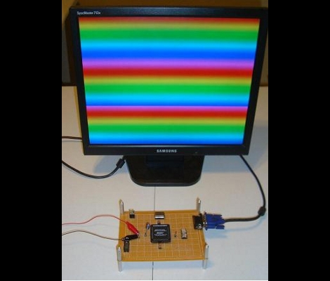
It seems like all the cool kids are leaving the 8-bit hobby microcontrollers in the parts bin and playing with more advanced parts like Complex Programmable Logic Devices. [Chris] is no exception to the trend, and set out to generate his own VGA signal using one of the beefy semiconductors.
It seems that he’s using the acronyms CPDL and FPGA interchangeable in his post but according to the parts list this setup uses an Altera EPM7128SLC84-7N CPLD. In order to generate the VGA signal he needed a way to convert the digital signals from the chip into the analog values called for in the video standard. He chose to build a Digital Analog Converter for the RGB color values using a resistor network which he calculated using PSpice. The other piece in the puzzle is a 25.175 MHz oscillator to clock the CPLD. As you can see after the break, his wire-wrapped prototype works exactly as designed. The example code generates the rainbow bars seen above, or a bouncing box demo reminiscent of a DVD player screen saver.
Want to know more about programming CPLDs? We did a tutorial on the subject a while back.
[youtube=http://www.youtube.com/watch?v=Tc572ygU70o&w=470]


I bet he had to replace the caps in that samsung monitor.
I tried doing something like this in school as a final project.. But I failed do to the restrictions on the project and chip. The chip had a max osciliator of 4MHz and that is no where fast enough to do any kind of processing for the chip to output on the screen… I was able to do a square pattern with just an on/off toggle.. I still got 100% on my project due to it being advanced beyond the class and I recognized where my limitations were…
I think this is a general trend actually. More and more are moving to programmable logic, and not just “the kool kids”.
I did this a few years ago on a Xilinx CoolRunner II board, but with a full framebuffer using external SRAM that I kludged to the expansion connectors, and a PIC MCU to (very sloooowly) load patterns or images.
I would have whipped up a write up on it, had I known they’d actually post something like this on hackaday :-/
No need for 25.175 MHz, if you happen to have a 50MHz oscillator (some of the Spartan 3 starter boards come with that IIRC), you can just divide it and use 25 MHz, most monitors are pretty tolerant of that.
Use a really crappy oscillator, however, and you won’t get a clean image.
Steve B,
Its sometimes better to have the correct clock, dividing with the internal logic eats up flip flops, and CPLDs don’t have nearly as many as FPGAs.
This is a bit overkill just for drawing some bars. Admittedly 512 colors is pretty good and the bouncing ball demo looks to run pretty smooth. However, you can apparently do a fair bit with een an Atmega32, like this guy did -> http://neil.franklin.ch/Projects/SoftVGA/ Also, this one that uses AVR with SDRAM -> http://tinyvga.com/avr-sdram-vga
@Steve B. Write that up and post it somewhere, please! I want to do something very similar.
BTW, how big was your buffer and what was your screen resolution? I need at least 384x224x2bpp (preferably 4bpp) for my project.
Some time go i build a pong game without a framebuffer. (on a DE nano) eache pixel is generated in sync with the vga update. mayby ik can find it back in my projects, and share it if someone is intrested.
@Amos, if I remember right, I had 128k x 8bit of memory, which would even be enough for 384×224 at 8 bits per pixel if you wanted.
I used Cypress memory chips, I either got a free sample, or got them pretty cheap from Digi-Key in an SOJ package, then soldered them onto little SOJ adapter boards and hand wired boards to connect them to female box connectors so I could connect them to the CoolRunner II board by ribbon cable. I actually still have them in a shoe box in my closet collecting dust.
If I dug up the software, I could probably have it working again pretty quickly.
I had two memory chips for double buffering, but I have some code for pseudo dual-porting by reading and writing on alternate clock cycles.
Maybe I can write something up for ya if I have some free time in the next few days.
Configurable logic is the future of complex digital systems. Soon, the software will be replaced by dedicated logic systems and the processing will be almost instantaneous, making real parallel processing computers. Now there are up to 3 GHz CPUs, but if you haven’t a 3 GHz data bus it is a nonsense approach.
@Steve B. that sounds perfect. Anything you can share would be great, and there’s no rush. Even just a few Verilog/VHDL snippets would be cool, just to give me a push in the right direction. Now I just need to find a cheap CPLD with enough I/O pins…
@Chris (PyroElectro) if you’re reading: Excellent site; thanks for sharing and keep up the good work!
@Amos
I posted my old pics and info to my otherwise very inactive blog for you, with a basic description of how it works, and a link to the whole VHDL source file that went into the CR-II. I didn’t go as far as making a proper schematic, and didn’t include external MCU source code, but I’m sure you can figure out what you’d like to do with that. If I were to do this again from the ground up today, I’d probably use a very different MCU anyway.
http://computer-nerding.blogspot.com/2011/05/turning-back-clock-summer-2007.html
I made a VGA controller back in 2004, it looked very similar to this, but I used a Xilinx XC9500 CPLD, an external SRAM to store bitmaps and an I/O port for a master system. I like it, but VGA is quite obsolete now.