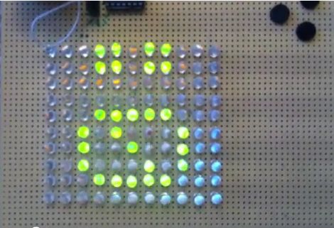
[Dmitry] was shopping for LEDs and accidentally pulled the trigger on the wrong type. Since he didn’t want to be wasteful, he figured he should at least take the time to build something with them.
A LED matrix display was the obvious project choice, but he only had a PIC16F688 at his disposal. Since the micro controller only has 11 output pins, charlieplexing was the only way he would be able to light the entire matrix.
While testing his LED array, he found charlieplexing to be a bit disappointing. The fact that the LEDs can get relatively dim, depending on the number of units lit at any particular time struck him as annoying.
In order to improve the performance of his charlieplexed array, he first decided to scan through all of the LEDs rather than just those that needed to be lit. This ensured that all of his LEDs had the same 1/110 duty cycle and were always as bright as possible. He also chose to use interrupts when lighting the LEDs. This meant that his code does not need to take into consideration any specific timing requirements to maintain persistence of vision. He also double-buffers the display to help reduce flicker.
He says that he ran into certain constraints with the PIC chip he chose, so he used a handful of lookup tables to ensure smooth operation of his display. He was quite satisfied with the results, and we think that the interrupt-driven display looks like it works just fine from where we’re standing as well.
Be sure to stick around for a quick video explaining and demonstrating his single-chip LED matrix.
[youtube=http://www.youtube.com/watch?v=yRYOYJx8LsI&w=470]


Note to haters: This is the same guy who rewrote the Palm TX ROM to take out most of the suck and replace it with nifty. What’ve you done that’s half that awesome?
Aaron, who are you talking to? No one, but you, has said a word about it yet.
I think he was leaving a pre-hater note.
Charlieplexing? Who the heck was Charlie?
Nifty concept. I should try to go all-out with the 24 port pins from my P1825K20.
This is awesome. Charlieplexing is great.
[Dmitry] also did a great writeup about the two microcontrollers he used.
@Ian: I just wanted to toss it out there in case anybody felt like going “oh lol charlieplexing 101 what a looser”.
@M4 et cetera: Wikipedia sez it was somebody called Charlie Allen who worked for Maxim. With 24 pins you could charlieplex up to 552 LEDs, which would be awesome.
“Note to haters: This is the same guy who rewrote the Palm TX ROM to take out most of the suck and replace it with nifty. What’ve you done that’s half that awesome?”
Put a Corvette LS3 engine in a Mazda Miata, I utterly destroy the wannabee Honda and Mitsubishi in town as well as Every Dodge challenger, charger, mustang that eve dares to rev at me.
What have you done?
Pre-hated haters.
fartface: Huh?
@fartface – that is impressive. Did you ever publish a how-to? I have a spare LS3 and would consider doing that too.
haters gonna hate
That’s the proper way to do it :) bookmarked
Awesome, fartface. Did you use Flyin’ Miata parts to do your conversion? FM weren’t the first ones to put an LS engine in a Miata, but with their help it’s a hell of a lot easier.
This project book marked, a Dimtry’s page lead to book mark two more outside of his.
Seeing how the comments got off track about haters. True, haters are going to hate, but that doesn’t mean they shouldn’t be called out on it. But if you decide to do so please don’t use too broad brush to determine hate.
It’s funny how you end up with the display technology that was used in the old 8bit systems like the appleII and c64 and such, a display driver scans a set of positions and you ‘poke’ values in the positions.
Full circle
Why would the LEDs get dim? Are they being driven right off the PIC? Why not have the LEDs connect to transistors and drive the transistors with the PIC?
i am running into this very problem driving 126 LEDs,; just not as bright as I would have hoped. I don’t have a lot of experience with the electronics… how would i use a transistor in the circuit? would i supply power to the LED’s seperately from my microcontroller? any insight would be greatly appreciated.
Look up charlieplexing on wikipedia paul, and specifically the ‘problems’ section.
Driving 552 LEDs with charlieplexing would result in a 1/552 duty cycle… that would be VERY dim unless you seriously overdrive the LEDs. For instance, if an LED has a nominal drive current of 20 mA to produce its standard brightness, you’d theoretically need to drive it with 552 * (20 mA) = 11 A to get the same apparent visual brightness… I doubt any LED would survive that.
I say with LEDs it’s “go bright or go home!”
there is no need to drive leds one at a time when charlieplexing
boost the each columns with an emitter follower, and do it like a regular matrix.