[Dino] Builds A Simple Non-contact Voltage Detector

homemade_voltage_detector

[Dino] is back with another installment of his Hack a Week series, and in this episode he is taking on what he promises will be the last transistor-based project – at least for a little while.

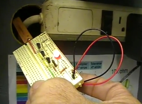
In the video embedded below, he shows off a homemade voltage detector circuit that he constructed using a trio of BC547 NPN transistors. The circuit is pretty simple though very useful all the same. At one end, the device has a small copper strip, which is connected to the base of the first transistor. The emitter of that transistor is daisy chained to the base of the second transistor and so on, until reaching the indicator LED.

As noted by one of [Dino’s] viewers, the circuit functions as follows:

“The front end copper strip forms one side of a capacitor, and then when you bring it near a voltage potential a super tiny current flows between air dielectric of the “cap”. This is mega amplified with the high gain BC547′s and viola, the LED lights up.”

Since the small bit of current is amplified many times over, the LED lights up even when very small voltages are present. While we might not necessarily trust our lives to [Dino’s] voltage detector, we’re sure it would come in handy now and again.

Continue reading “[Dino] Builds A Simple Non-contact Voltage Detector”

Lxardoscope Is A Linux+Arduino Oscilloscope

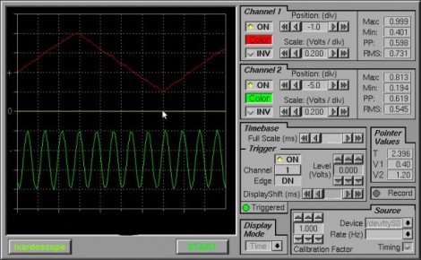
[Privatier] wrote in to let us know about lxardoscope, his project that lets you use an Arduino as hardware input for a Linux-based oscilloscope display. This implementation offers two channels with about 3000 samples per second from each. He touts some of the GUI options like vertical resolution between 2mV and 10V per division. That part kind of stumps us because we don’t see how a measurement of 10V (or more) can be taken using the schematic included. But you’re comprehension may surpass ours so do take a look yourself.

He is using an Arduino Uno for his testing. But to get around some issues he’s experienced with other USB-based solutions he implemented a serial port connection instead. You’ll need to remove the ATmega chip from the Arduino board after flashing the code to it, and then build a circuit around it which includes a power source where -2.5V is ground and 2.5V is VCC. All in all, you’ll need a 16 Mhz crystal, HEF4069 hex inverter, ATmega8-family microcontroller, and a few passive components to build this on a breadboard.

PIC LC Meter Improvements Add Li-Ion Battery And Charging Circuitry

[Trax] needed an LC meter and decided to use a tried-and-true design to build his own. The only problem was that he didn’t want to be tied to a bench supply or power outlet, which meant a bit of auxiliary design was in order. What he came up with is the battery-powered LC meter you see above.

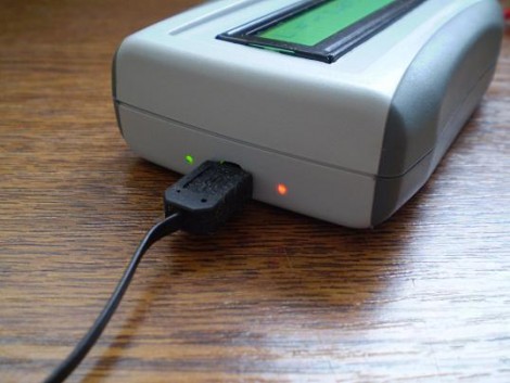
The core of the original [Phil Rice] design remains the same, with slight modifications to drive a different model of character LCD. The code is mostly unchanged, but some calibration routines became necessary after [Marko] noticed bugs in the behavior after power cycling. Now the device will perform what amounts to a hardware reset about 700ms after powering on or changing between inductance and capacitance measuring functions. The project box is quite small, and to get everything to fit [Marko] sourced the Lithium Ion battery from a Bluetooth headset. He needs 5V for the LCD screen so he used a TPS61222 boost converter. To top off the battery he’s included a MAX1811 single-cell Li-ion charger, which has a couple of status LEDs visible through the case as seen above.

[Thanks Marko]

Laser Light Show Comes To Life From The Junk Bin

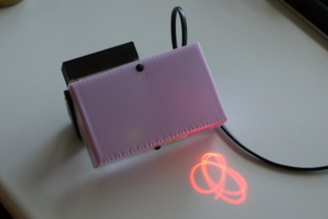
In a project that only spanned about three weeks [Lars] built this laser light show projector using parts scavenged from his junk bin. We’ve seen the concept many times before, all you need is a laser source and two mirrors mounted on a spinning bases. The laser diode for this project was pulled from a recordable DVD player. That beam passes through the optics from a laser printer to give it the focus necessary to get a good projected image.

[Lars] played around with the mirror angles until he achieved just the right look. The first mirror is mounted about 4 degrees from being flat with its motorized base; the second is off by about 6 degrees. This introduces slight oscillation in the beam direction when the motors are spinning. By adjusting the speed of each motor you get different patterns. Adjustments are happening completely at random thanks to the BasicStamp2 microcontroller which hadn’t been used in years. Fifteen lines of code were all it took.

Want a laser that’s not controlled at random? Check out this addressable galvanometer-based show.

Adding An External Audio Input To The Sansa Clip+

adding_external_mic_input_sansa_clip

Workshop 88 member [Jim] got his hands on a couple of SanDisk Sansa Clip+ MP3 recorder/players from Woot, and was anxious to see what he could do with them.

The first order of business was to install RockBox, an open source hardware package built for a wide range of MP3 players. He was impressed with how robust the firmware was, though he thought the Sansa’s built-in microphone could use a bit of upgrading. Acting on a tip from a fellow square dance enthusiast, he disassembled one to see how he might add an external audio input.

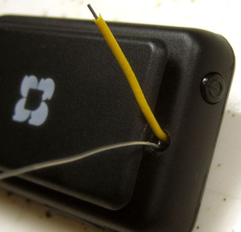
He pried the existing mic apart, and desoldered it from the motherboard, installing a small capacitor and resistor in its place. He extended some wires through the case, then powered up the unit to make sure it was still alive and well. Since things still looked good, [Jim] put some audio on the Sansa’s new inputs and sure enough it recorded the audio without a hitch.

He says that his initial guesses for the capacitor and resistor values were pretty decent, though with a bit of tweaking he should be able to get exactly the recording levels he was looking for. Not bad for a $20 audio recorder!

ATtiny Hacks: BEES! An Electronic Scale To See Who Brings In More Honey.

[MakingThingsWork] wanted an accurate way to keep track of the weight of his beehive, so he decided to build himself a data logging electronic scale. First he ripped the strain gauges from an old electronic scale which he then fitted to his home made beehive base. He then went about designing and building the control board which is based about the Attiny 85 (if you hadn’t guessed by the banner). An instrumentation amplifier was used to amplify the signal from the strain gauge, which is then read by the ADC on the Attiny. It looks like he had some trouble getting consistent results from the scale, so to eliminate the error caused by temperature variations he set up a fixed voltage divider for reference. With this setup the scale can produce results at +/- 0.5lb accuracy, sounds just fine for a system that cost less than $50. The V-usb project software has been used to connect the scale to his PC which he uses to collect and graph the data. All in all a very neat project and by the looks of it, some very productive bees.

8 Breadboard Hacks To Make Life Easier

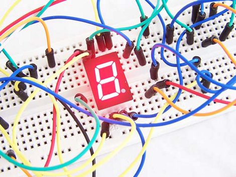
If you like messing around with electronics, one of the best tools you can have on hand is a solderless breaboard. These handy little chunks of plastic just let you “plug n play” so you can quickly develop a circuit before committing it to solder and fiberglass. Handy as they are, they do have their downsides such as:  stuff not fitting, split up power rails, running out of jumpers or just taming what can quickly become a birds nest of a mess.

Luckily the folks over at [Proto Stack] have published a handy article giving us 8 Breadboard Hacks. While anyone that has used breadboads for any length of time will have probably figured most of these out, its still good knowledge for any newcomers to the sometimes aggravating world of plastic and jumpers.

Also we know there are more hacks you can do to make your lives easier and would love to hear them in the comments.