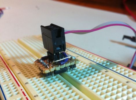
[Quinn] over at Blondihacks has been working with AVR microcontrollers a lot recently, and wanted a quick way to program the ATtiny13a (her current AVR of choice) while the chip is still seated in a breadboard.
To speed up code revision and testing, she built a small programming header that she calls the Bread Head. The device is wonderfully simplistic, consisting of little more than snappable header pins and a bit of upside-down protoboard.
She soldered six headers to the top (formerly the bottom) side of the board, while a set of eight oversized headers were soldered to the opposite side of the programmer. Small bits of wire were soldered in to connect all of the appropriate pins together before [Quinn] slipped the header snugly over the top of the ATtiny and gave it a quick test. Everything worked perfectly, so she slathered in in epoxy for sturdiness and called it a day.
She says that the programmer works so well that she’s likely to make a similar header for other common AVRs too.


I use such adapter a long time, too, but mine is a little bit smaller.
There are a couple places where you can buy a kit for exactly such a device, and quite cheaply too. You can get them for any AVR here, and this guys sells a couple as well. The difference being that these kits have a socket for the AVR, and come with filter caps, etc.
Of course, DIY is fun, too…
I like the allgaiershops breadboard apapters. He sells on eBay too. I think the total price is around 50 cents cheaper when you buy on eBay. I wish he made an inexpensive V-USB board.
Sparkfun sells one pre-assembled with an ATTiny85 for about $10. Or is that too expensive? (I know it’d be too expensive for me, but I’m just cheap)
I can do that too!
http://cmjdev.tumblr.com/post/10893117782/new-breadboard-setup-utilizing-the-isp-breakout
A little closer view
http://cmjdev.tumblr.com/post/10847776282/now-that-the-new-cnc-mill-is-working-awesome-ive
Everything that makes life a bit easier!
Wow, great idea, why did I never though of that ._. Creativity is simple.
identical hack found on the net: http://c2.com/cybords/wiki.cgi?BreadboardSpider
personally I still stay with messy louse cables as I don’t program uC that much, and change uC from project to project
Great idea! I built a breakout cable that breaks out 6 pin ISP into 6 individual lines, but it broke because I used thin wires. I should build one of these for the ATMega168 series chips, would be incredibly useful.
Cool, a close friend of mines has been doing this for a while now:
http://ghmicro.com/index.php?option=com_content&view=article&id=26:avr-programming-cable&catid=21:projects&Itemid=4
Yes, but the emphasis of this is that it doesn’t require the extra breadboard space that you’re going to occupy nor the extra effort it takes to wire the ribbon socket to the chip.
This design straddles the chip. You can simply leave the first hole open for each of the required pins, push it into place in the breadboard and program it.
One of the other links in the comments showed a breadboard populated with just mcu’s along the center slot, and that this header design makes it easy to just go down the line, rapidly programming the chips.
There “were” commercial versions of this and they co$t in line with exotic commercial stuff for the ones that weren’t junk flimsy. The “Plastic Hinge” made of Nylon tended to get brittle faster if a bench had antistats that generated a bit of ozone. Or natural sunlight for extended hours. This design eliminates those issues.
Quinn has a winner here. Points scored for overall utility and creative application of stuff that’s often in our working gear boxes. Scalable up or down is my initial thought.
SMD IC size ranges might be a worthy challenge too.
I’ve made one of these too. Mine is even more basic: just a 2×6 piece of stripboard with 4 header pins pointing up and 4 pointing down. It saves a lot of breadboard spaghetti, but it did once cause me to spend ages to figure out why an avr wouldn’t program when there was a tiny bridge between the pins on it.
I like my version better.
http://www.flickr.com/photos/oohshiny/3375280312/
Cute!
It would be much easier to use a standard IC test clip:
http://letsmakerobots.com/files/userpics/u10562/clip.jpg
The DIP versions are cheap, but anything smaller is still outrageously expensive.
I’ve made mine to contact directly on the DIP chip. It wasn’t meant for the breadboard, just for a board where i forgot the ISP header. But it has better use. It’s a bit bigger because it is for programming 28 pin DIP.
Hey everyone! I love all the variations on this idea that everyone has. Lots of great solutions to this problem. For me, I wanted something that allowed me to leave the uC in the breadboard, and something that allowed me to leave the ISP connected. That way I can iterate quickly on the hardware and software at the same time. Thanks for sharing your versions, and thanks for the post, HaD.