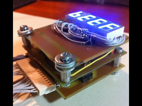
[Quinn Dunki] is looking to augment the tools she has available at her electronics bench and built the HEX Out as a mock-logic sniffer. The device reads 8 or 16-bit inputs, showing the current state of those connections on a 7-segment display. This requires that you’re comfortable reading Hex codes, but if you’re not it’s almost like studying flash cards; before long you’ll be able to read them without thinking about it.
She’s blogging about the design and build process in three parts. The link above is the first installment where she shares the development process for the top layer which hosts the display hardware. The other two parts should be up for your enjoyment in the next couple of weeks.
You’ll notice her design on this portion of the project still requires a lot of point-to-point soldering, even though she etched her own circuit boards. We didn’t look too closely, but it seems this would be worth going to the trouble of etching a double-sided board if you can.
UPDATE: Part Two is now available


nicely done Quinn.
If someone has a nice design for a single-sided PCB to break out 7-segment display pins, please share. Ideally, it would not require running traces between pads, for easier home etching. That latter requirement is a tough one, and the pin arrangement on seven-segment displays hurts my brain. Thanks for the post, HaD! :)
It shouldn’t be too hard? Using an IC/per segment akin to an DM9368 or MC14495? Heck even some old-school HP 7-segs like HDSP-0962 – I though there was a HaD article on these once, can’t find it… Worst case, use some really cheap mCUs like PIC/ATiny.
I’m not sure if my question was very clear- I’m interested in how people would lay out the traces to get seven-segment display pins broken out into a linear header. Is it possible to route those traces efficiently on a single-layer board without running traces between pads? Inquiring minds want to know…
Awesome! Only the data buffer and magic code trigger are what I’d really need to have, as my buses normally are faster than my eyes, otoh the max freq for the circuit must also be known…