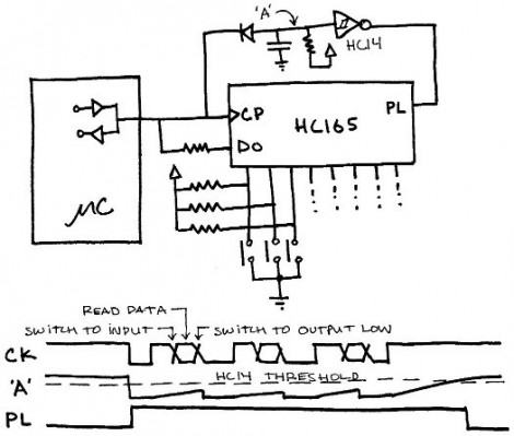
Here’s an interesting article about reading data from shift registers using less than three pins. 74HC165 shift registers are a popular choice for adding inputs to a microcontroller. They have a parallel input register which can be read using the latch, then shifted into a microcontroller via the data and clock pins. For those counting, that’s the three pins normally associated with driving these devices.
This hack first does away with the latch pin. The addition of a carefully trimmed RC circuit (capacitor is charged by the clock pin, then the resistor lets that cap slowly discharge) means that the device will not latch until after the clock stops toggling. This technique drops the control down to just two pins (data and clock). You can still use hardware SPI to read the data using this method. It’s the same as using SPI to drive 595 shift registers except the microcontroller reads data instead of writing it.
But wait, there’s more! The diagram above actually shows a way of reading this shift register with just one pin. Notice that the clock and data pins are now connected to just one of the microcontroller pins. The data pin has an added resistor, which keeps the current low enough that it will not compete with the clock signal coming from the microcontroller. In between clock pulses, the microcontroller switches from output to input to read the data pin on each cycle. Give it a try, it’s a fun experiment!


That’s pretty nifty and useful, gotta keep this in mind when I am short on pins.
Brilliant
This is insanely cool. Though my guess is the tolerance on the circuit has got to be pretty tight.
Very swish. Respect to the designer.
About 6 months ago here I saw a variation, using similar technique so that some 8-pin chip could run a second LED off the same pin.
I don’t remember who/when details, but specifically I remember they used a cap and a resistor to enable selection between the two LEDs. I wish I had bookmarked it then… love these clever tricks.
Sure you aren’t thinking of charlieplexing?
Thanks, no, it was def. not charlieplexing. Maybe I saw the link at adafruit come to think of it. It was def. a resistor,cap, and a small pic or avr. The cap allowed fast flicker of 1 led without triggering the other led which shares the same pin, all due to charge time and bleed.
It was an EDN Design idea; I had posted it to the Arduino Forums, and you might have seen it there. Slightly different (used the inherent pin capacitance and hysteresis instead of adding them explicitly.)
http://www.edn.com/article/518373-Drive_16_LEDs_with_one_I_O_line.php
Note that since the shift register used doesn’t have a separate latch, all the values will shift out all the pins at some point. Fine for steady-state indicator LEDs, but perhaps not for other things.
Thanks WestfW – this was the one I was thinking of. I remembered it a little differently (I thought there was a cap in the circuit), but I recognize the page. This is very clever stuff, and a pity it’s not something I’ve found in my introductory electronics books.
The link is no longer good. Can you upload a description it again?
http://www.openmusiclabs.com/learning/digital/input-scanning-matrix/hacks/index.html
http://www.edn.com/search?keyword=SearchDrive_16_LEDs_with_one_I_O_line.php