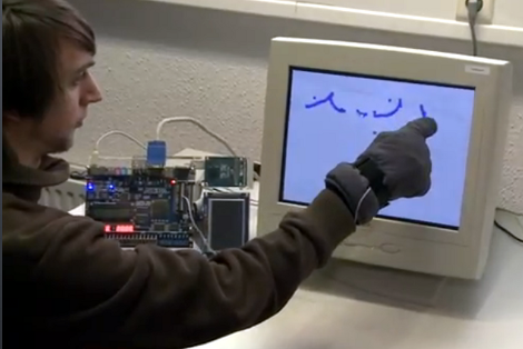
Here’s a bulky old CRT monitor used as a touch-screen without any alterations. It doesn’t use an overlay, but instead detects position using phototransistors in the fingertips of a glove.
Most LCD-based touch screens use some type overlay, like these resistive sensors. But cathode-ray-tube monitors function in a fundamentally different way from LCD screens, using an electron gun and ring of magnets to direct a beam across the screen. The inside of the screen is coated with phosphors which glow when excited by electrons. This project harness that property, using a photo transistor in both the pointer and middle finger of the glove. An FPGA drives the monitor and reads from the sensors. It can extrapolate the position of the phototransistors on the display based on the passing electron beam, and use that as cursor data.
Check out the video after the break to see this in action. It’s fairy accurate, but we’re sure the system can be tightened up a bit from this first prototype. There developers also mention that the system has a bit of trouble with darker shades.
[youtube=http://www.youtube.com/watch?v=HNXDjwqBhNY&w=470]
[Thanks Luc]


Nifty to be done in an FPGA, but This is exactly the same thing as the C64 light pen, and every light gun for every gaming console up until LCD TV’s became a thing.
The old HP 16500 logic analyzers have CRT touch screens.
Interesting new take on the old Light Pen interface, for which many old video cards in the 1980s and 1990s had an interface (which was usually an unpopulated header).
In those days, the few programs that were designed to use light pens would overcome the problems that these guys are having (like false positives and difficulty detecting touch) by always displaying a bright box that would indicate where you could touch, and blinking the box a couple of times when you used the button on the pen, not only to give feedback to the user but also to verify that the detected location was correct. This was also important because many monochrome monitors used phosphor that had a long decay time.
Actually, light pens date back to the ’50s
I am really digging the FPGA projects.
It’s a light pen.
I had a light pen on my Atari 800, nearly 30 years ago. It connected via the joystick port and was pretty cool, although there wasn’t much software available to use it.
I want, nay, NEED to use this to play Duck Hunt with my finger as the gun.
Also so you can point at someone with your finger and go “Pew pew pew!”, I’d imagine.
Buy an NES light gun, take apart, glue guts to a glove, done!
I’m really the first one to say “Minority Report”?
I made a light pen for my c64 about a year ago, was a pretty cool trick. I think the neatest part was being able to read out the exact position of the electron beam at any point.
This explains the screen system the library had.
They had small wire-attached pens that they pointed to the screen, with a button on the side. Much like old pen digitizers but wired. When you pushed the button the whole screen would flash.
Oh what fun we had before the mouse…
Funny you should bring that up, actually. at least on the C64, it was easier to implement a light pen than a mouse, at least for me anyway.
Agreed nice new twst on a old hack. I did this with a VIC-20 LOL
Neat!
(Used the wrong “Their/There/They’re” in the last sentence.)
So how is the position actually measured? Timing from start of hor. sync. for h. position, and timing from start of vert. sync for vert. position?
Since the FPGA is driving both the graphics and reading the sensors, it doesn’t matter. The FPGA always knows what pixel is being scanned out.
Thanks.
In the old days you got one interrupt which was the screen refresh interrupt. You couldn’t easily get one for each line.
So, basically, you start a timer on the screen refresh interrupt, and stop it when the light pen reports it has seen light (i.e. the electron beam just lit up the screen under the pen tip). Simple maths divides the line scan time into the total time to give the number of complete lines (the quotient) and the distance from the beginning of the current line (the remainder).
Naturally it’s a bit more fiddly than that, but a lot of it is magicked away by low level hardware.
Ok, now it’s clearer. This method looks tricky for very high precision, since one horizontal scan takes only 50-60 microseconds.
Actually, the responsibility for capturing the time can be passed to the video generator chip (analogous to the FPGA here). Here is an article about handling the data from a 6845 video controller:
http://www.doc.mmu.ac.uk/staff/a.wiseman/acorn/bodybuild/BB_83/BBC8.txt
As you can see, the video controller snapshots its own counter when the light pen detects the electron beam. Then you need some software to translate the register contents into actual screen positions.
Wow! Take a look at this :
http://projects.csail.mit.edu/video/history/aifilms/105-museum.mp4