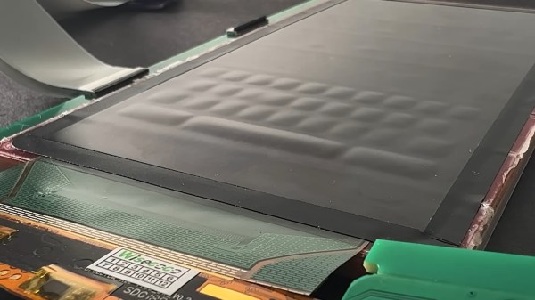
An image of a powered-off device screen. Part of the screen is raised in the configuration of a mobile keyboard. A ribbon cable extends from the left of a PCB underneath the screen and the PCB extends below the bottom edge of the screen with a sticker that has a stylized manufacturer logo that may read "Wisecoco."

Electroosmotic Haptics For More Tactile Touch Devices

If you’re like us, one of the appeals of retro tech is the tactile feedback you get from real buttons. Researchers at Carnegie Mellon have developed a new method for bringing haptic feedback to touchscreen devices.Labeled exploded view of the device stackup. The individual layers from top (output) to bottom (reservoir) are labeled Silicone, PCB & Electrodes, Adhesive, Glass Fiber, PET, Adhesive, PCB & Electrodes, Adhesive, Delrin, Adhesive, and PET. It also shows the different parts as sections of Output Layer (silicone), Pumping Layer, and Reservoir Layer (Adhesive, Delrin, Adhesive, PET).

Using an array of miniaturized electroosmotic pumps, the current prototype devices offer 5 mm of displacement from a 5 mm stackup which is a significant improvement over previous technologies which required a lot more hardware than the displacement provided. When placed under a flexible screen, notifications and other user interactions like the keyboard can raise and lower as desired.

Each layer is processed by laser before assembly and the finished device is self-contained, needing only electrical connections. No need for a series of tubes carrying fluid to make it work. Interaction surfaces have been able to scale from 2-10 mm in diameter with the current work, but do appear to be fixed based on the video (below the break).

You might find applications for haptics in VR or want to build your own Haptic Smart Knob.

Continue reading “Electroosmotic Haptics For More Tactile Touch Devices”

A Soft Thumb-Sized Vision-Based Touch Sensor

A team from the Max Planck Institute for Intelligent Systems in Germany have developed a novel thumb-shaped touch sensor capable of resolving the force of a contact, as well as its direction, over the whole surface of the structure. Intended for dexterous manipulation systems, the system is constructed from easily sourced components, so should scale up to a larger assemblies without breaking the bank. The first step is to place a soft and compliant outer skin over a rigid metallic skeleton, which is then illuminated internally using structured light techniques. From there, machine learning can be used to estimate the shear and normal force components of the contact with the skin, over the entire surface, by observing how the internal envelope distorts the structured illumination.

The novelty here is the way they combine both photometric stereo processing with other structured light techniques, using only a single camera. The camera image is fed straight into a pre-trained machine learning system (details on this part of the system are unfortunately a bit scarce) which directly outputs an estimate of the contact shape and force distribution, with spatial accuracy reported good to less than 1 mm and force resolution down to 30 millinewtons. By directly estimating normal and shear force components the direction of the contact could be resolved to 5 degrees. The system is so sensitive that it can reportedly detect its own posture by observing the deformation of the skin due its own weight alone!

We’ve not covered all that many optical sensing projects, but here’s one using a linear CIS sensor to turn any TV into a touch screen. And whilst we’re talking about using cameras as sensors, here’s a neat way to use optical fibers to read multiple light-gates with a single camera and OpenCV.

Continue reading “A Soft Thumb-Sized Vision-Based Touch Sensor”

Fabric(ated) Drum Machine

Some folks bring out an heirloom table runner when they have company, but what if you sewed your own and made it musical? We’d never put it away! [kAi CHENG] has an Instructable about how to recreate his melodic material, and there is a link to his website, which describes his design process, not just the finished product. We have a video below showing a jam session where he exercises a basic function set.

GarageBand is his DAW of choice, which receives translated MIDI from a Lilypad. If you don’t have a Lilypad, any Arduino based on the ATmega328P chip should work seamlessly. Testing shows that conductive threads in the soft circuit results in an occasional short circuit, but copper tape makes a good conductor  at the intersections. Wide metallic strips make for tolerant landing pads beneath modular potentiometers fitted with inviting foam knobs. Each twist controls a loop in GarageBand, and there is a pressure-sensitive pad to change the soundset. Of course, since this is all over MIDI, you can customize to your heart’s content.

MIDI drums come in all shapes and sizes, from a familiar game controller to hand rakes.

Continue reading “Fabric(ated) Drum Machine”

E-Book Reader Gets Page Turn Buttons, Is None The Wiser

Most e-book readers don’t have physical page turn buttons. Why? They just don’t. Virtual page turns are accomplished with a tap at a screen edge. Determined to reduce the awkwardness of one-handed use, [Sagar Vaze] modified a Kobo e-reader with two physical page turn buttons as a weekend project.

[Sagar] points out that since the underlying OS of the Kobo device is Linux, it is possible to fake touches to the screen (and therefore trigger page turns) by recording then replaying the appropriate input event. However, there was a more direct solution available to those willing to tamper slightly with the hardware. Touch sensing on the screen is done via an infrared break-beam system. Along two edges of the screen are IR emitters, and opposite the emitters are receivers. Broadly speaking, when a fingertip touches the display a minimum of two IR beams are broken, and the physical location of the fingertip can therefore be determined by analyzing exactly how the IR pattern has been changed.

To spoof page turns, [Sagar] briefly shorts two IR emitters: one on each axis. The sudden winking out of the IR is interpreted by the device as a crisp tap, and the device obediently turns the page. The only hitch is that both IR emitters must be shorted at the same time. If one is shorted before the other, the device ignores it. Double-pole switches would probably do the trick, but with the part bin coming up empty in that respect, [Sagar] instead used a few transistors to accomplish the same thing. A 3D printed enclosure rounds out the whole mod, and a brief video is embedded below.

Continue reading “E-Book Reader Gets Page Turn Buttons, Is None The Wiser”

What’s The Cheapest Way To Scan Lots Of Buttons?

So you’re building a new mechanical keyboard. Or attaching a few buttons to a Raspberry Pi. Or making the biggest MIDI grid controller the world has ever know. Great! The first and most important engineering question is; how do you read all those buttons? A few buttons on a ‘Pi can probably be directly connected, one for one, to GPIO pins. A mechanical keyboard is going to require a few more pins and probably some sort of matrix scanner. But the grid controller is less clear. Maybe external I/O expanders or a even bigger matrix? Does it still need diodes at each button? To help answer these questions the folks at [openmusiclabs] generated a frankly astounding map which shows, given the number of inputs to scan and pins available, which topology makes sense and roughly how much might it cost. And to top it off they link into very readable descriptions of how each might be accomplished. The data may have been gathered in 2011 but none of the fundamentals here have changed.

How do you read this chart? The X axis is the number of free pins on your controller and the Y is the number of I/Os to scan. So looking at the yellow band across the top, if you need to scan one input it always makes the most sense to directly use a single pin (pretty intuitive, right?). Scrolling down, if you need to read 110 inputs but the micro only has eight pins free there are a couple choices, keys E and F. Checking the legend at the top E is “Parallel out shift register muxed with uC” and F is “Parallel in shift register muxed with uC“. What do those mean? Checking the table in the original post or following the link takes us to a handy descriptive page. It looks like a “parallel out shift register” refers to using a shift register to drive one side of the scan matrix, and “parallel in shift register” refers to the opposite.

Continue reading “What’s The Cheapest Way To Scan Lots Of Buttons?”

E-Dermis: Feeling At Your (Prosthetic) Fingertips

When we lose a limb, the brain is really none the wiser. It continues to send signals out, but since they no longer have a destination, the person is stuck with one-way communication and a phantom-limb feeling. The fact that the brain carries on has always been promising as far as prostheses are concerned, because it means the electrical signals could potentially be used to control new limbs and digits the natural way.

A diagram of the e-dermis via Science Robotics.

It’s also good news for adding a sense of touch to upper-limb prostheses. Researchers at Johns Hopkins university have spent the last year testing out their concept of an e-dermis—a multi-layer approach to expanding the utility of artificial limbs that can detect the curvature and sharpness of objects.

Like real skin, the e-dermis has an outer, epidermal layer and an inner, dermal layer. Both layers use conductive and piezoresistive textiles to transmit information about tangible objects back to the peripheral nerves in the limb. E-dermis does this non-invasively through the skin using transcutaneous electrical nerve stimulation, better known as TENS. Here’s a link to the full article published in Science Robotics.

First, the researchers made a neuromorphic model of all the nerves and receptors that relay signals to the nervous system. To test the e-dermis, they used 3-D printed objects designed to be grasped between thumb and forefinger, and monitored the subject’s brain activity via EEG.

For now, the e-dermis is confined to the fingertips. Ideally, it would cover the entire prosthesis and be able to detect temperature as well as curvature. Stay tuned, because it’s next on their list.

Speaking of tunes, here’s a prosthetic arm that uses a neural network to achieve individual finger control and allows its owner to play the piano again.

Thanks for the tip, [Qes].

Industrial 42" multitouch pc

Hacking An Industrial 42″ Multitouch PC

We’re slowly moving in the direction where everyone will have a touch screen desk like in the 1982 TRON movie or in the 1987 Star Trek: The Next Generation series with its ubiquitous touchscreen starship controls. [FFcossag] lucked into that future when a local company offered him an industrial 42″ multitouch PC that they were throwing out. A few hacks later and he has us all suitably envious.

Before hacking away though, he had to take care of some magic smoke. The source of this turned out to be yellow goop on the PC’s power supply that had turned conductive across a resistor. Cleaning it fixed the problem.

Moving on to the hacks, he added brightness control by using a potentiometer to control the power to the backlight. Be sure to watch carefully in the video below where he’s attaching a magnet and cord to the potentiometer, and encasing it all in epoxy. At that point, we’re pretty sure we see him spin up a hard drive platter with a sandpaper disk attached to it, forming a bench top disc sander and making us like this hack even more.

He also replaced a small speaker with a larger speaker and amplifier, giving a volume and sound quality difference that’s like night and day. He also added a breakout board with relays for power management, eliminating a seven watt continuous draw when in standby mode.

Be sure to watch the video to the end where he leaves us with a tour of the hacked interior hardware. We like how he’s labeled all his handiwork for any future hacker who might open it up

Continue reading “Hacking An Industrial 42″ Multitouch PC”