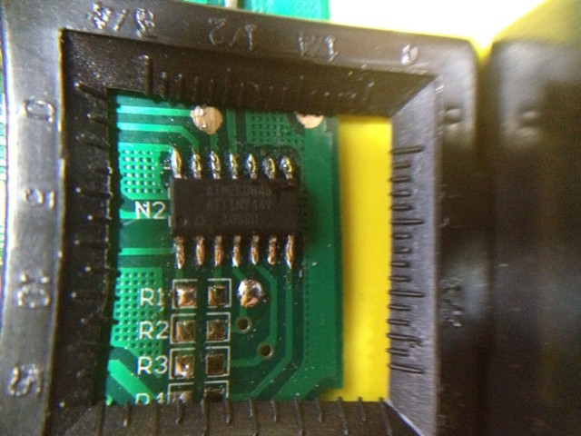
The Ikea Dioder is an LED light sold at the big blue and yellow building that lets you mix your own colors using a simple button and wheel controller. [Marco Di Feo] looked at all of the other projects out there that alter the controller and figured out that the IC can be directly replaced with an ATtiny44 microcontroller. With that chip soldered onto the board he added IR control so that he can change colors using his universal remote control (translated).
[Marco] removed the potentiometer normally responsible for selecting the color. This frees up one pin on the microcontroller which he then uses to receive signals from a TSOP1736 IR receiver. The video after the break shows the device, which illuminates the back of his home entertainment center, reacting to commands from his remote control.
Of course this can be done without the chip swap as the PIC 16F684 that comes with it can be reprogrammed in place. But [Marco] didn’t have a PICkit or other programmer on hand.
[Editor from the far future: video has gone private. Sorry about that.]


It is neat to remove the pic chip. However, for those interested using the device as is; I wrote complete new firmware for the dioder using the standard 16f684. The firmware does 256 step pwm on all channels, implements several operational modes, has extra mode-led outputs and saves setup in the pis’s eeprom.
It also has a serial input (1200-8n1) on one of the unused pins to control it remotely.
My friend wanted to be able to choose two colors to cycle through only – say, purple and red, and have it just fade between the two, or fade out of one and into the other. I see your firmware has some advanced modes with extra button combos, but it was unclear if it supported that. (I don’t know what “LEDs cycle through the HSV cone” means).
My plan was to keep the functionality almost the same, but replace the harsh color cycle mode (ID 2 “step” on your firmware) with the mode that would cycle through two colors. Press and hold the button at the first color, move the wheel to the second color, and then release the button. It would then cycle between those colors.
However, implementing it any other way in your firmware would be fine. I guess it occurred to me that I’m not sure conceptually if you even *can* cycle between purple and red at constant intensity without getting other colors as you cycle. I mean obviously you’d get whatever colors result from mixing red and purple. Well maybe it is possible then? I mean, you’re not going to get yellow for example.
Anyway, do you know how to easily implement such a mode?
Red and purple are next to each other in the color circle (H-parameter in HSV). So, you can simply move the H-value from red to purple and then back to red.
This can be easily implemented in mode 7, which is unused at this moment. You should be able to identify the entry-points for that part (mode7_step and mode7_init; to enable init, you must add the call to jumptable modeinit_table). At init you set the HSV values to an initial color, then at each step you change the H-value in the direction you fancy.
For the HSV model see wikipedia HSV color model and <a href="http://en.wikipedia.org/wiki/File:HSV_color_solid_cylinder_alpha_lowgamma.png" title="HSV color cylinder"
My focus was the IR receiver that gives me the ability to control the dioder remotly. The pic replacement was only necessary, because i don’t have a pic programmer and the first version of my software with ir and pwm was running on an atmega8 with uart.
Nice hack. I guess he’s more accustomed to AVR and didn’t want to program a PIC. He could have made a PIC programmer with his AVR :)
This article and the original page is missing the C code! This must be corrected immediately!
As an ATMEL guy myself I can see the appeal here. I’ve never used a PIC and if I don’t have to learn thats really fine with me. I’m sure there’s not much to it, but if all I have to do is find a compatible part I’d be inclined to just to that. Still, seeing Bertho’s comment above about a complete replacement firmware, maybe I’ll give that a go.