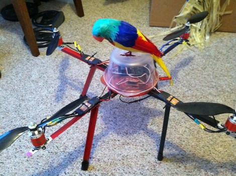
When working on his quadcopter project [Matt] decided it would be best to build a robust controller for the device. He had never sent off a PCB design for fabrication, but took the plunge and ended up with a compact and reliable PCB on the first try.
One of the first things that comes to mind when we hear about quadcopter controllers are the feedback sensors. The accelerometers which are used for these projects generally come in a DFN or QFN package. This means there are no legs. Instead the chip has pads on the bottom of the package making it a lot more difficult to solder. [Matt] side-stepped this issue by using an IMU board which already has the sensors in place and offered a 0.1″ SIL pin header to use as an interface. This is simple to roll into the design, along with all of the other connectors for motor control, power, etc. He grabbed a copy of Eagle Lite to do the layout, and used OSH Park to get the boards fabricated. He was surprised that everything worked on the first try. Thanks to his planning it fits inside of a plastic food container where it should be able to ride out most minor crashes with ease.


