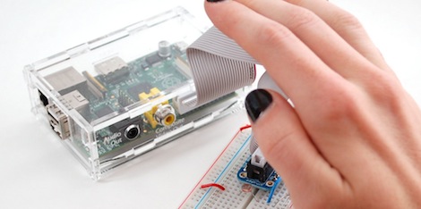
Adafruit just posted an awesome tutorial on reading analog sensors with the Raspberry Pi. It’s a great walkthrough that can be applied to your next Raspi project as well as any project where you just need one more analog input.
Earlier, the folks over at Adafruit posted a tutorial on using a MCP3008 ADC with the Raspi to directly read analog values using a Raspi. Sometimes, though, you don’t need eight analog inputs and a 12-bit ADC to get a project off the ground. Adafruit’s tutorial for reading analog values without an ADC relies on a single 1μF ceramic capacitor attached between a digital input and ground. By pulling the sensor line high for a millisecond or two, the capacitor charges at different rates depending on the value of the analog sensor.
Yes, it’s just an RC timing circuit but seeing as how the Raspi doesn’t have an analog input, we figure this tutorial could help out a few people.


it’s just an RC timing circuit
Then why title it Reading analog sensors with the Raspberry Pi?
Because that is what she is showing people how to do?
Because maybe someone isn’t that familiar with the RC time concept and this would be a good learning experience ?
Well, I wanted what the title says and Google led me here and I am satisfied. So it’s a good title.
Someday I’ll get my Raspi – someday! I ordered it, paid for it. Some day they will ship it!
I’m surprised — I ordered my 3 on July 18th and they’ll be here Monday (July 30th)
I ordered my Raspberry on August and received on December :D.
Just go with the ADC, much easier to code around!
“By pulling the sensor line high for a millisecond or two, the capacitor charges at different rates depending on the value of the analog sensor.”
Aren’t you supposed to pull the sensor line LOW–to drain the capacitor, then reading the charge time?
Isn’t it how older joystick ports worked on older PCs ?
yes, thats what i was going to say.
analog joystick ports on desktop PC’s before USB f***** everything up was just a simple RC circuit and thats why often (VERY VERY OLD) fast computers needed to have the CPU slowed down in order to work with VERY old software that used the joystick…
(and expected the CPU to slow down its attempts to read the joy,[EDIT: the entire software?] later on, CPUs were so fast there was no more assumed delay)
and hence the turbo button.
which should have been called “slowdown” and had the logic inverted for the LED ect…
and because component values have a stronger effect on RC cuircits, explains why calibration every day is important… room temperature 25c -OR- 45c has big difference
The other reason for slowing down the CPU when playing games (e.g. slowing a 286 down to 4.77 MHz) was because the games often had assumptions about how fast they were, so if the CPU was too fast the Space Invaders would come down and kick your ass before you could shoot back at most of them.
Yes it is ant it’s a PITA!
Better off with one of those I2C ADCs that Microchip are doing at around a dollar less CPU better accuracy and speed repeatability etc etc
Bitbanging SPI in userspace in python again, are we? For gods sake that ADC has a kernel driver already, all you need to do is write a tiny platform code glue to make it ‘mysteriously appear’.
formerly known as the Apple II paddle controller circuit..
Might be good to at least add a comparator circuit to make the threshold consistent and avoid scary metastable regions in the digital inputs, but I guess it will probably work okay either way.
i love that shit. In the past i used the arduino…now i am happy :-)