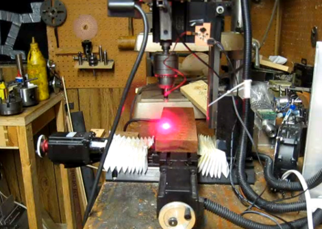
[Smells of Bikes] wanted to add laser etching to the list of tricks his home CNC setup is capable of. He has a diode which will work for the task, but he needed a driver that could be interfaced with the CNC system. He ended up designing a driver board based around the LM3402 chip.
Now driving one of these laser diodes isn’t all that different from driving a Light Emitting Diode. He chose to use the LM3402 chip because he’s the TI engineer who designed the official evaluation board for the part. It’s meant for high-power LED applications, and the 700 mA he needs for the laser is within spec. Since he’s soldering by hand, and this part has a ground pad on the bottom, he shares his soldering technique in detail. Once the driver board is ready, he uses a ‘sed’ command to replace the g-code Z axis commands with digital on/off commands to switch the diode.
Check out the demo video after the break. He uses a diffuse beam since the cutting beam is bright enough to damage his camera.
[flickr video=http://www.flickr.com/photos/9279759@N03/7786350966/ w=470]


Looks like I’ll need to find a laser to put in my mill!
Ebay. Get an entire module. I tried getting just the diode and a separate lens and putting them together. That was a disaster.
Also make sure you get a glass lens for any laser diode over about 100mW because plastic lenses don’t seem to last long.
“He uses a diffuse beam since the cutting beam is bright enough to damage his camera.”
Nevermind about his eyes, worry about the camera…
Do not look into LASER with remaining eye.
But how else can you tell it’s on? ;-)
Seriously. If he’s using a laser, where’s his goggles? If he’s got goggles, put them in front of the camera! o.O
I only have the one pair of goggles, which I was wearing. Even with a diffuse beam I end up with a headache if the laser’s bouncing around the room.
When I’m actually running this I put up an opaque beam blocker and the whole workshop is still flashing red inside. Clearly I need to match the beam wavelength better to the cutting material.
(Interesting sidelight: the laser will cut dark materials immediately, but if I’m cutting paper, like making stencils, it takes about 4 seconds at focus for the paper to go black, but once it does the CNC can run at nearly G0 rates, much like oxyacetylene cutting, so I have to add dwell commands.)
Quite normal isn’t it? Dark materials will absorb light and light materials will reflect it :)
100mw will not damage the camera. Not from diffuse or specular reflections.
Awesome. I was just trying to talk my bud who built a laser into doing this. MOAR please!!
For all things Laser head over to photonlexicon. They are a very serious bunch but don’t let that put you off!
The LM3402 / 3404 are really quirky chips IMO, we did a design with them recently that had to work with a selection of LEDs and they do not work with varying resistances of load. Hence, IMO, they are not constant current drivers as they are labelled as.
The reason for this is they do not use hysteresis on their CS pin, they trigger on rising edge of voltage on CS, then wait for a time determined by the R and C you tie to them, then switch back again. Your value of R and C is calculated using a “known” Vout which makes this a sort of pointless constant current. Fine if you are sticking it on a board with an LED that’s not going to change.
You have been warned.
Excellent work, and nice to see a pro writing up a project using free tools when state of the art software is available at the office.
Interesting thermal pad technique. I guess there is sufficient thermal path to keep the die cool. I had the same problem with a different TI part, TAS5704, but that required a good few cm2 of copper pour. I ended up making a double sided board with a ‘thermal via’ of stout copper wire. I soldered it on the top side and sanded it almost flat. Then fluxed the bottom of the chip before soldering it down, flipping the board and soldering the bottom of the via with a big iron. The heat goes up the copper melting the solder under the chip. http://yfrog.com/3v64pinj
“n with actual laser goggles, if I look at the burn spot for any length of time I see spots.”
What is the OD of your goggles? If you are seeing spots at 100mw something is wrong. My goggles for green make my 7 watt 532nm look like an LED.
Really you should have OD 7, at least.
Here’s another way to cut off a laser or other LED in a milling/router setup: http://www.jcopro.net/2012/02/06/cnc-light-painting-some-refinements/ – cuts off based on the “Z” position similar to how traditional engraving stops when the axis gets too high.
There is no way you are only getting 100mw out at 700ma. There are only a couple red diodes that can handle that much current. I’m assuming you are using a 300mw mitsubishi 635nm diode. Running at 700ma you must be getting at least 250mw with a 3-element glass lens. The 300mw 635 diodes are also multimode, which isn’t a good choice for this application because the dot cant be focused down as small as a single mode laser can.
I suggest you switch out the a 12x 405nm diode. Run it at around 400ma. Its single mode, the wavelength is absorbed much better than red by most materials, and it will be higher power than this diode.
https://sites.google.com/site/dtrlpf/home/diodes/s06j-12x-405-diodes
Use the MAX3600 or new 3601 to drive the lasers. It’s got a DAC input and you can modulate the pulses to get a clean output. Handles up to 1A.