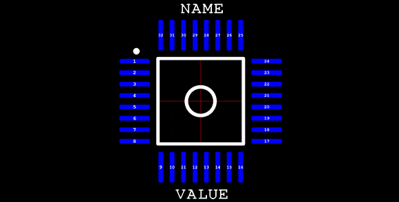
Making new parts in Eagle CAD isn’t the easiest thing in the world, especially if you’re dealing with a package that isn’t in one of the default libraries. Usually, making a new part means digging out a datasheet and drawing a new part in Eagle. A better solution would be to generate new parts with code – define the number of pads, the shape of the pads, the symmetry of the chip, and so forth. [Joost]’s madparts does just that, allowing anyone to create new parts in Eagle by entering numbers instead of drawing lines.
The idea behind madparts is to code new entries in Eagle libraries with Coffeescript. It has instant graphical feedback for the part you’re designing, and is able to import from and export to Eagle libraries. A KiCAD-enabled release is coming soon, but until then, madparts looks like a great way to create your own parts in weird packages in Eagle.


Cool thing, parts creation has been a headache in EAGLE.. However, this feature has been standard in DesignSpark since the initial launch about 4 years ago. I believe that you can export from DS to EAGLE as well…
whats wrong with make-symbol-device-package-bsdl.ulp ?
Here you have an actual programming language you are defining your footprint in instead of the plaintext used by make-symbol-device-package-bsdl.ulp.
This allows you to make mods & calculation in your footprint script meaning you get a self-documenting effect.
Also you get immediate visual feedback during coding.
The footprint in coffeescript is supposed to be the base format, not just something you use once. Need an adjustment, just adapt the coffeescript, press ctrl-e, refresh the library in eagle, and done. Need an adjustment as a separate footprint, clone the script, adjust, export to cad, done.
[disclaimer: I wrote the program]
Kicad.
After 15 years of using proprietary packages professionally, I am glad to say that the new Kicad is now my package of choice. A lot of time is spend familiarizing yourself with packages and I’d recommend to any newcomers and old timers looking to change their existing systems to have a look at this open source, multi platform package. Open source has finally produced a good PCB package,, much better than the ones I use to use.
I can’t wait for it to get into KiCAD, this is one of the biggest features I’ve been missing from Altium.
Awesome, I’ll give this program a shot the next time I need a new part (which is becoming more and more frequent…). My biggest headache though is mislabeling pins on the symbol, and/or mapping it to the wrong pad on the package :( no matter how many times I doublecheck, I always seem to have something wrong that only becomes apparent 3 seconds after I send the PCB off for fab :P
amazing! Will try this out next time I make a new part…
I’d happily be writing a Kicad export module right now… but my dev machine is opengl 1.4 only. :(
Today I released version 1.1. Mostly a bug-fix release but it does have a hugely simplified installation for win32 and linux. More details at http://joost.damad.be/2013/05/madparts-release-11.html