Visualize Twitter With An LED Matrix

visualizing-twitter

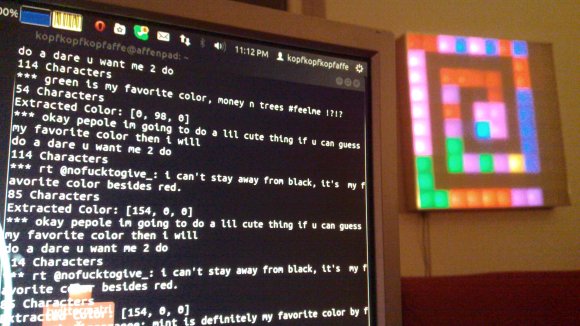
What’s your favorite color? Don’t tell us, Tweet it to [Sebastian’s] favorite color Twitter display and you’ll be contributing to the artwork hanging on his wall.

This answers a very important question, what do you do with your projects after they’re completed? For us the best part is the planning and building. Once it’s done the thrill is pretty much gone for us. We haven’t even switched on our Ping Pong clock in over a year. But [Sebastian] recently dusted his 10×10 LED matrix for this project.

Tweets are parsed by a Python project he wrote to try out the Twitter API. It looks for a set list of colors . He asserts that people aren’t that creative when you solicit their favorite color but to prove him wrong we’re going to say our favorite is Amaranth. After it finds the color it pushes it to the next pixel in the spiraling pattern shown above. But wait, there’s more! To give the pixels a but if extra meaning he uses the total length of the tweet to set intensity.

If you need a Titter enabled hack that displays a bit more specific data you’ll want something that can actually display what was Tweeted.

Building RAM Into Veronica – The 6502 Computer

ram-for-veronica

It seems strange that RAM is being added to a computer so late in the build, but [Quinn Dunki] must have had it in the back of her mind the whole time because it turns out to be a rather painless experience. For those of you keeping score, this makes her Veronica project Turing complete.

The brightly colored rats nest pictured above connects the new components to the 6502 computer backplane seen in the upper left. [Quinn] decided to go with two 32K SRAM modules which need very little in the way of drive hardware (it’s hanging out on the breadboard to the left). The RAM module will simply listen for its address and react accordingly. There is one hitch regarding a two-phase clock and the need to protect the RAM from erroneous data during the first of those phases.

Getting this all to work actually pointed out a bug in the ROM module she had long ago completed. After picking up on the problem she was able to correct it simply by cutting traces and soldering in jumper wires.

Images Carrying An Encrypted Data Payload

encrypted-data-image

This is a tidy looking banner image. But according to [Ian] it contains 52KB of source code. You can’t just read out all of that data. Well, you can but it will be gibberish. Before hiding the bits in plain sight he encrypted them with two different keys.

He’s using AES-256 encryption to keep his data away from prying eyes. But if that wasn’t enough, he also wrote a PHP program to hide the bits in a PNG image. Not just any picture will do (otherwise your eye will be able to see something’s awry). The post linked above focuses mainly on how to choose an image that will hide your data most easily. We asked him if he would share his techniques for actually merging the encrypted file with the picture and he delivered. Head on over to his repository if you want to take a look at the generator code.

Add Features (that Should Have Already Been There) To An EPROM Programmer

extending-an-eprom-programmer

[Morten Overgaard Hansen] has a cheap EPROM programmer which he uses to program chips for retro gaming (among other things). He was surprised that although the device includes a 40-pin ZIF socket it seems to lack the ability to program 16-bit chips. He figured he could get it to play ball if he put in a little effort. Above you can see that a few add-on parts enabled 16-bit programming on the device.

If you look inside the case you may be surprised to find it uses an FPGA. [Morten] searched around and found a few others online who had been looking to stretch the functionality of these types of programmer. Specifically, he came across a Python program for this programmer’s bigger bother that already implemented the functions necessary to program the larger chips. He used it as a guide when writing his own programming application.

On the hardware side of things he needed to feed a higher voltage to the VCC pin, which is done with the boost converter seen to the right. He also added some jumper wires to manage the output enable signal. To make the whole thing modular he ordered a ZIF socket with long pins and soldered the alterations in place. Look closely and you’ll see two levers for ZIF sockets. The one on the right is for the original socket, the one on the left is for the adapter.

Building A Wooden Air Raid Siren

siren

A while back, [Matthias] was working on a dust collector for his shop. Being the master woodsmith he is, he decided to build a dust collection system out of wood. Everything worked out in the end, but in creating wooden impellers and blowers, he discovered his creations made a lot of noise. For this project, instead of trying to quiet his blower, he decided to make one as loud as possible in the form of an air raid siren.

The basic idea behind [Matthias]’ air raid siren is to make two impellers that force air through two stators along the perimeter of the rotor. As the siren spins, the air coming from the impellers is either blocked or passes through the stators, creating an alternating high and low pressure; to be more accurate, it creates a ton of noise. Stack two of these impellers together and you’ve got a two-tone air raid siren made out of wood.

For something that’s spinning very fast, we’re surprised [Matthias] didn’t have more problems with balancing his siren than he did. There are a few useful tricks to be picked up from his tutorial, though: balancing everything on a marble really seemed to help with the build.

As for how loud the siren is, [Matthias] can’t give us a decibel volume. From the video after the break, though, we can tell you it’s really, really loud.

Thanks [Dimitar] for sending this in. [Matthias], it’s alright if you send projects in yourself. You’ve earned the right to say, “I am so cool!”

Continue reading “Building A Wooden Air Raid Siren”

Coding New Parts In Eagle

chip

Making new parts in Eagle CAD isn’t the easiest thing in the world, especially if you’re dealing with a package that isn’t in one of the default libraries. Usually, making a new part means digging out a datasheet and drawing a new part in Eagle. A better solution would be to generate new parts with code – define the number of pads, the shape of the pads, the symmetry of the chip, and so forth. [Joost]’s madparts does just that, allowing anyone to create new parts in Eagle by entering numbers instead of drawing lines.

The idea behind madparts is to code new entries in Eagle libraries with Coffeescript. It has instant graphical feedback for the part you’re designing, and is able to import from and export to Eagle libraries. A KiCAD-enabled release is coming soon, but until then, madparts looks like a great way to create your own parts in weird packages in Eagle.