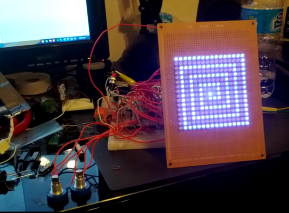
This project is a wonderful example of what can be accomplished with a rather complicated logic circuit. It’s an Etch-a-Sketch made from a 16×16 LED grid. That in itself is only somewhat interesting. But when hearing about the features and that it is driven by logic chips we were unable to dream up how it was designed. There’s no schematic but the video commentary explains all.
The thing that confused us the most is that the cursor is shining brighter than the rest of the pixels. This is done with two different 555 times and a duty cycle trick. When you turn the trimpots the cursor position is tracked by some decade counters. Pixels in your path are written to a RAM chip which acts as the frame buffer. And there’s even a level conversion hack that let’s the display run at 15v to achieve the desired brightness. Top notch!
[via Reddit]


cool project and that the dual clock trick is a nice idea …
now waiting for the first comment to suggest to use a certain italian designed board :)
Pizza board?
Ciabatta Board?
Some other kind of bread board?
Cool project, but why not make the wiring a bit neater? Unless this is temporary or he is moving to a permanent board, he should probably make it neater, I know I would (or try at least).
Also, fyi hackaday these comment fields are all in white again so you can’t see what is being typed.
Very neat project. I love seeing people take the road less traveled with electronics. I look forward to his RGB version.
There’s no…end to how annoying that is? There’s no…telling how many fewer articles get read? There’s no…worse way the layout could be fouled up short of flashing gifs and auto-playing music?
The hack’s pretty sweet.
Sweet! But, as commented before, this could have been made with an italian board much more easily. Unless you need to do things at the sub microsecond level, for a complex logic like this a microcontroller is king.
And what exactly would be learned from ‘cheating’ in this way? Any monkey can copy code.
Why would you use a microcontroller ?
It’s so easy to program you could probably do this in 30 min.
Where’s the challenge in that ?
Very cool bare metal sort of logic. Reminds me of using oscillators for autonomous insectoid robots motion control instead of complex programs.
Beautifully thoght up and beautifully executed.
“Why not use a microcontroller?!!1” Because the point is to use discreet logic? Sometimes you want to do something challenging like this just for the challenge of figuring out how the hell to do it.
Very nice project! A cool addition would be to use the screen itself as the input device. LEDs can be used as photodiodes, but I don’t know how complicated the readout would be if done purely in logic. The cursor would run across the screen and the LED next to it would be used to check if it got light reflected by the finger.
bad solution: use an IR LED behind each visible LED with either free formed second layer or use clear circuitboard
okay solution: use smd with IR/visible close together, each pixel(R.G.B.IR.) farther apart
good solution: invent an LED that has R/G/B as well as IR built in!!!
which brings a whole new class of dual display… hmm
hint: CCD camera picks up IR
secret messages.
blocking recording of a video display (“white screen” picture for IR swamps visible)
inappropriate messages only for adults (ccd camera owners) think advertising for ciggerettes andor booze ect…
for the record, in my area it is illegal to advertise ANY brand-name or price of any tobacco what-so-ever. PERIOUD. they cant even “LEGALLY” tell me which pak is the cheapest (althou they often do)
in my area, BY LAW, they are supposed to hand you “the book” of tobacco prices and brands instead of telling you which is cheaper.
OR they can check your age/id FIRST and then SCAN a random brand YOU specify to get you to purchase it (assuming it is not the cheapest) at which point you can see the price and then get them to scan another brand… waste of time!
online stalkers can now gooogle where i live. blahblahblah
Just found the link I had in mind : http://cs.nyu.edu/~jhan/ledtouch/index.html
Maybe it is possible to do the scanning for input fast enough so it does not disrupt the displaying of the actual image.
I’m amazed that anyone would even ask the question “why?” The real question is, “why not?” Play is the essence of creation, and clearly this guy is a master who understands what he is doing. Fantastic.
I love that no micro was used. Reminds me of all those projects I built in college. It was rare to use a microprocessor. Well at least back in the day it was.
This kind of work has mostly been replaced by CPLD and FPGA design these days, but its exactly the same kind of hack that Steve Wozniak used for the Apple II video generator circuit (clocked logic reading SRAM and writing to a display). He might want to try playing about with FPGAs, even an entry level device has enough grunt to implement a 32 bit CPU with VGA output, plenty of capacity experiment with.
Many times I see people with fancy Arduino or FPGA kits that they made do something, then say “Look what I built!”. They didn’t build anything they just programmed it. Logic is the way to go.
I like etch a sketch and paint by numbers, how about you? http://www.segmation.wordpress.com