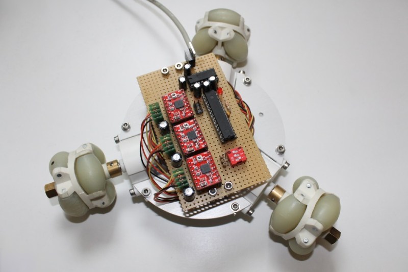
Machinist, electronics engineer, programmer, and factory worker are all skills you can wield if you take on a project like building this omniwheel robot (translated).
The omniwheels work in this tripod orientation because they include rollers which turn perpendicular to the wheel’s axis. This avoids the differential issue cause by fixed-position wheels. When the three motors are driven correctly, as shown in the video below, this design makes for the most maneuverable of wheeled robots.
An aluminum plate serves as the chassis. [Malte] milled the plate, cutting out slots for the motor with threaded holes to receive the mounting screws. A few stand-offs hold the hunk of protoboard which makes up the electronic side of the build. The large DIP chip is an ATmega168. It drives the motors via the trio of red stepper motor driver boards which he picked up on eBay.
So far the vehicle is tethered, using a knock-off of a SixAxis style controller. But as we said before, driving the motors correctly is the hard part and he’s definitely solved that problem.


Very impressed with how well the omnidirectional control works, I once programmed a Picaxe to control tank tracks by a traditional RC car stick controller (left stick = forward/back, right stick = left/right) and that took some serious thinking to get the code right for smooth control.
P.S. THANK YOU VERY MUCH FOR RETURNING COMPLETE ARTICLES TO THE FRONT PAGE!
I shall be clicking on the articles again now, for reading/posting comments & the embedded videos.
Nice, and lots of detail in the original post.
Mmmm must get around to building my own…
Very nice build, I took a crack at one of these with modified servos but had so much trouble mounting them and getting a good stable axle for the wheels it all fell apart (literally) Going to have to try and take another stab at it after seeing this.
This is awesome! I love how those wheels work, it’s almost hypnotic to watch them seem to defy physics. I have seen wheels like that before (can’t remember the name) but they looked more complicated like the ones on Mythbusters’ forklift.
Also thanks for fixing the front page! The flow is back! :)
They are called ‘mecanum wheels’.
Would not these wheel create high friction when the bottom is maneuvered perpendicular to one of those wheels?
Sure, if the motor isn’t rotating it will have friction when moving in that direction … and that’s how it’s supposed to be. Wheels can’t do much without friction.
would the same math apply to something more compact like this perhaps??
[IMG]http://i43.tinypic.com/ok4tq0.png[/IMG]
I’m imagining some of it would but your force vectors are going to significantly change because of the placement of the wheels, Think of the simplest example: moving a linear direction with 2 wheels going the same speed. Now do that on your model, it’s probably going to spin in a wide circle.. also the 3rd wheel not moving is going to steer it funny, much more complicated but as you said more compact also. Certainly not impossible though!
A beauty of a project but a major job.
Looks great but without access to all the tools needed Ill build one of wood and mules to power it. (joke)