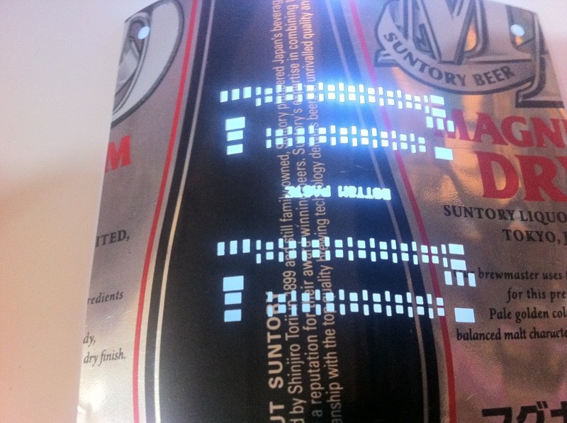
This is a solder paste stencil machined from a beer can. [Simon Ludborzs] spent quite a bit of time dialing in his process to get to this point. Note the nice crisp edges of the openings. That’s a big change from his first attempt.
When looking for a way to make his own stencils he considered two options: plastic and aluminum. He produced both (more about the plastic stencil and his reflow process is discussed in this post). Plastic is a bit easier to work with since it lays flat. But it proves to be too thick. After applying paste with a squeegee there’s way too much solder on the pads. Aluminum beverage can walls are much thinner, depositing less paste.
We’ve seen soda cans used in the past, but they were produced through an etching process. [Simon] cut these holes using a CNC mill. This required a bit of futzing to figure out the right settings. For instance, he used Altium to produce CAM files from his circuit design. But the program is set up to mill the outside of traces, resulting in openings that are too large. He fixed this by setting the pasted expansion rule in the program to a negative value. The other advantage to using a mill is that he can cut precision tooling holes to ensure proper alignment. You can see them in the upper corners of this image.


I had a hard time parsing the title.
I was wondering WTF was a machining beer and how it could solder stencils.
lol this was my laugh of the day :)
maybe one day we will be drinking beer and soldering stencils at the same time..
I am drinking stencils and using beer for solderring.
What do you mean “maybe one day”… hic.
Now there is an idea I’ll drink to!!
http://youtu.be/ACgJhE2L7Ms?t=46s
I’m surprised I haven’t seen anyone 3d print a solder stencil yet. You’d think you could parse your design files right into g-code for your printer. With a little work I bet you could get it pretty thin too.
Printing small openings is notoriously difficult. For one, the plastic will shrink as it cools and the amount of shrinkage will vary depending on the size and shape of the opening. Also, the first layer is usually squished into the bed a bit harder to promote sticking which makes the shapes of the first layer slightly distorted (a circle will become smaller because the plastic gets squeezed towards the center of the circle etc etc).
Then you have the limitation of nozzle size. A common size is 0.4mm which means that 0.4mm is the smallest string of plastic you can squirt out. Add in the unpredictable shrinkage of openings and the first layer being squished and you can see where this gets complicated real fast.
Getting it thin isn’t a problem. A decent printer will easily do 0.1mm layers.
Getting thin might also be a problem. I believe 0.1mm (=~4 mils) is already around the max. thickness for fine pitch stencils.
This is absolutely false.
You can easily print 0.2mm with a 0.4mm nozzle. I’m printing 0.1mm with a 0.35 nozzle on my printrbot. If you fiddle with the settings a bit you can make the first layer non squished.
The inside dimension theory is true however. It is far harder to control the inside of a shape than the outside, but that can be calibrated out after a few attempts.
My issue would be getting the large, very thin, flat print off the print bed.
I forgot to mention in my post that the narrowest pad hole is only 0.4mm (and 1.5mm long).
How will a 3D printer manage with type of spec?
On the other hand, once the solder melts its pretty forgiving / self aligning.
Seems like if you are working at this level of precision you could swap out the spindle for a paste squirting device and forego the beer can altogether.
Do you know where I can buy one of those? It should be able to squirt fine enough for those tiny pads of course. We are that level of precision.
On the reprap forums there are people using medical syringes (non-prescription from any drug store) to put solder paste on pcb’s, they might mention the gage needle and size of the syringes they are using on their forums.
There’s actually an easy way to make Aluminium cans flat, it involves a Sandwich maker ;)
Here’s an instructable I wrote a while back about how to do it (I was flattening them to do papercraft out of Aluminium): http://www.instructables.com/id/Papercraft-with-Aluminium-Cans/
Thanks for the top tip
I’m going to try flattening some cans soon, and I’ve been wanting to tackle a papercraft project some time too.
The ideal endmill/burr for this would be a lefthanded flute righthanded cut bit, yes they do make them, but are rather special (read rare) items. That way it would push the chip down & not lift the aluminum up.
Sounds like you got your offset and directions mixed up, in conventional milling a pocket where the waste is on the inside of the toolpath, your toolpath should be counterclockwise and the offset should be on the left. Climb milling visaversa, clockwise toolpath, offset on the right.
This is a great idea…IF you just happen to have a CNC mill laying around.
I would like to hear the speeds and feeds he used for milling as well as the geometry of the cutter. I want to try it on my mill and it would be a leg up to know these things as a basis to start milling with.
tried to ask the poster directly on the linked-to site, but unless you have a google+ account, there is no way to email him and ask the question.
Hi
Sorry but I have no idea – I’m using an LPKF Protomat C30S which is a dedicated PCB mill, and I’m just using it’s defaults. Heck, I don’t even know if I can alter the defaults…
And I’ve disabled the Google+ comments now too.
How do you mount the aluminium can to the mill? Does it need to be super flat?