A little light reading means something different to us than it does to [Hamster]. He’s been making his way through a book called The Scientist and Engineer’s Guide to Digital Signal Processing written by [Steven W. Smith, Ph.D]. Being the hacker type, a million different uses for the newfound knowledge popped to mind. But as a sanity check he decided to focus on a useful proof of concept first. He’s come up with a way to filter out the mains hum from Analog to Digital Converter samples.
Mains hum is all around us; produced by the alternating current in the power grid that runs our modern lives. It’s a type of interference that can be quite problematic, which is on reason why we see EMF sensor projects from time to time. Now you can filter that ambient interference from your projects which take readings from an ADC. This would be quite useful for applications which measuring teeny signals, like ECG hacks.
[Hamster] did a pretty good job of presenting his demonstration for the uninitiated. He even provides examples for Arduino or FPGA projects.


You can also buy ADCs with built-in 50/60Hz filters. I often use the AD7792, especially for interfacing RTDs and thermocouples.
How do you interface it with the Arduino? The Adafruit 16 bit is easy, but the AD7792 has a few more connections. Thank you for your reply.
I think his arduino code has a bug. sensorValue is miscomputed. It should be total/4, not sensorVal/4.
@arlet thank i’ll keep AD7792 in mind.
D’oh. fixed that!
Mike, I see you are now dividing total by 4 but you still have the LED controlled by sensorValue (which is unset).
Also, as Totoxa mentioned, you seem to be implementing the rolling average incorrectly – working on 4 values at once and then moving on to another set of 4 values instead of “rolling”, a value at a time through 4 consecutive samples. You might add a new value [say n] and remove the oldest value [n-4] and then divide by 4 to get the average of the current 4 values. You could do this all in sensorValue since that will maintain it’s value between loop evaluations.
Argh! I should stick to VHDL! :-)
Yes, If you wanted continuous samples you could roll the values through the filter.
However, if you have an analogue temperature sensor that you might want act on it only once a minute then it isn’t worth it, as only four values will end up in the number that will be acted on.
I guess the point I was trying to make is that you easily remove the 1st and 2nd of any 50Hz noise with an average of just four samples, as long as they are 5ms apart.
Not trying to bust you too hard. I think it’s a useful point to make. :-)
The arduino code is wrong…
after 4 inputs the buffer is reseted. The current code after in the fifth input have a delay and then averages the 5th, 6th, 8th and 9th input but it should average the 2nd, 3rd, 4th and 5th input. The 16ms delay should only happen at the start…
At 1200 samples per second, you can average 120 samples and get good cancellation for both 50 Hz and 60 Hz (assuming you can tolerate the 100 ms delay and have enough RAM).
Averaging over 1/10 of a second will work, but on the downside you will also filter out most of the frequencies between 5Hz and 50Hz too..
I would rather sample at 300Hz, and then pass through a 5 sample moving average (removing all the 60Hz), and pass that output into a 6 sample moving average (removing all the 50Hz).
It will only need a quarter of the sample rate, the latency will be around 50ms, and it will only filter out 15% of the 10Hz component.
The moving average is easy to implement and provides total suppression as long as the sampling frequency is properly tuned to a multiple of the mains frequency. I like his filkter but that’s my usual approach.
Nice article! That book is a good one – I bought three copies as it’s very reasonably priced as well. It ought to be known as the “the awesome blue book of dsp”, and apart from the diagrams, most of it is online at dspguide.com
To the parent above: Don’t forget that the sample clock needs a defined phase relationship to the mains for this exact cancellation to be true – if its derived from a crystal, you’ll get an offset drift as the mains isn’t exactly 50/60Hz. (even if you used an atomic clock). That offset drift can be a killer at low sample rates – it will make you a fairly large, slowly changing offset that can be plus or minus quite a bit – say perhaps 100mV – from minute to minute or even second to second – or much worse, day to day. (You “calibrate it out” one day, then it’s shifted the next.)
The best possible approach is to sample about three and a half orders of magnitude faster than the highest frequency you really care about, and using a passive second-order low-pass bessel analog antialiasing filter. Set the -3dB point of that filter so that the rejection reaches the quantisation noise floor of the sampler at half the sample rate. (ie, very very aggressive/crazy-conservative “guard band” – just like a lock-in amp does). Then run the resulting high sample rate through a long truncated-gaussian FIR filter.
If you’re doing transient analysis (hint: almost everyone actually is, if you want to know what the sensor says “now” for some value of “now”, then you’re in the time domain.) then rather than downsample, instead truncate.
Once gaussian filtered (and assuming your passive filter works and keeps any aliased-component radio energy out) then you know that each sequential sample cannot change by any value greater than the peak coefficient at the middle of your gaussian-FIR filter. So any higher order bits can be just dropped, without losing the ability to “undrop” them later. (assuming, of course, that you don’t loose any stretches of data).
Use a relay to short the inputs together while you bring up your ADC and filters – that way you know where you’re starting from, which is all you really lose by truncating off the higher order bits. Ie, you might handle +/-5V max, but each sample doesn’t need to know that. After you’ve got data moving, and before you start analysis, release the relays and let the natural step response of the ADC system bring from you up to your true “initial value”.
The step response of such a system (zoomed out, of course) looks very much like a square wave. It’s not – actually the sample rate is many times more than the “time precision” you actually need, but this is good. For calculations involving the data, take the error in time to be the standard deviation from the width of your FIR filter, as this will be the same as the edge transition time of any step response anyway.
Of course – probably overkill for just about any application that doesn’t need high time precision, but it’s about the only way to have both good “value” precision as well as a well-defined “temporal” precision.
If you decimate, you run afoul of the fact that a continuous-time edge doesn’t necessarily happen synchronously to your final choice of sample rate.
The problem is that the frequency response of the nice data described above is a mess, it looks much like a gaussian, with seemingly insignificant sidelobes that drift on and on, attenuating only relatively slowly. If you fed your nice square-wave test signal in, you’ll get a FFT that resembles a sinc function.
If you try to get more shannon-nyquist channel efficiency, by setting the -3dB point of your analog anti-alias filter to, say, 0.45fs (I’ve even seen 0.55fs) then the energy in the aliased components will integrate wrong in the digital filters – because one sample glitched out of place by a lucky sum of co-incident aliasing components at the exact moment the sample was taken (looks like a heap of “spikes”) will throw the average at the lower sample rate far wide of the true average energy of the signal. With dodgy analog anti-alias filtering, little “glitches” can and do sneak in, mostly because you’re unintentionally “downsampling” radio energy.
And this will throw your whole filter off, by more than you’d expect. Particularly bad is “spark noise” such as comes in particularly obtuse mains-harmonic edge series. (Eg, edges from that simple triac light-dimmer circuit) If your sample rate happens to end in a 0, then it has high order harmonics in phase with these series, and they will add to undo what attenuation you thought you could get away with on your ADC input.
If you do this, then no amount or type of filtering will save you – the aliasing caused by decimation is a nonlinear distortion, so no linear filter jujitsu can fix it.
There are 24-bit sigma-delta chips around, that go one worse, and run a windowed-sinc FIR filter before decimating the data before presenting it to you. There are “lab-grade” daq systems using this chip, without ANY analog anti-aliasing filters. They achieve performance that might have been just as good as if they’d just sampled at 6 bits to begin with, and called it a day.
Back on topic:
A good approximation of a gaussian FIR is just to run four moving averages, one on the next’s output. It’s easy, and it works really well. If you’re in an fpga, it’s more efficient to use cascaded-integrator-comb filter, (also known as a SINC^n filter, somewhat confusingly – its impulse response is not a sinc, its frequency response is. ) which is essentially the same thing, reorganized to use less adders – just remove the downsampling that’s usually put in the middle, between the integrators and the combs. (google CIC filters)
Also couple of gotchas for moving average filters: Don’t forget to initialize your moving average filter by taking the first value output to be just the first value, the second to be the first + second /2, etc. If you don’t initialize properly that way, you’ll get an offset error that changes every time you restart the filter, because most of your averaged-values will probably start as not-real zeros, and this will throw the sum off by a bit every time.
And finally, use fixed point math please! floating point computation does really odd things with moving average filters – they tend to drift all by themselves, due to the variable quantization error. Fixed point doesn’t do this, so as long as you’ve taken care of gotcha #1 above, you’ll be spot on.
The feeling of learning 30 things while your mind explodes… I have found it. I’m going to have to bookmark this one!
is your adc device connected to the tv cable? by cable modem, video capture device or even firewire or usb connected to cable box to download streams or even via hdmi?
if so that may be the problem it is ground loop.
i solved it by using a cheater plug to disconnect the ground on the power (mains) and then use the tv cable as the ground instead.
ground loop happens when the tv cable is grounded away from the computer ground and some electric is being induced in the ground wire.
if you have a ups or some kind of protection device it may complain of a wiring fault and that is normal for the fact there is no ground prong connected
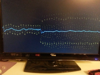
The wire on the ADC is just a 20cm male-male jumper wire, with one end attached to the ADC connector, the other hanging free.
It is just picking up hum from free space…
Forgive my ignorance if I am wrong here, but is it possible you are creating a ground loop in your sensor setup? I remember having a lot of erroneous sensor values when my machine (CNC in this case) and my any auxiliary equipment made a ground loop.
At the moment I’m deliberately introducing the mains hum – just a dangling wire on a high impedance input.
However I’m intending to build a optical pulse oximeter, and given that the sensor will be a long way away from the electronics I wanted a way to remove the hum that is bound to get picked up and amplified along the way to the ADC.
The running course of ece4760 (available on youtube) deals exactly with biological sensors and noise reduction. Might be a worthwhile watch, especially the filtering and EMI courses.