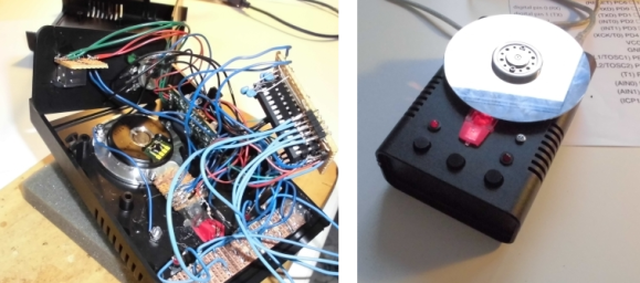
If you’re reading this blog then chances are you have a dead hard drive hanging out somewhere in your house. Here’s a weekend project that will put it back into use. [Andreas] took on the popular project which combines a hard drive and optical mouse to build a scratch controller.
The gist of the build is that you use an optical mouse sensor to track the movement of the platter. But [Andreas] made things harder on himself by not using the USB capability of the mouse and mapping it in software for his needs. Instead he plucked the sensor from the mouse, reading it using an Arduino. After much trial and error with the best way to coat the underside of the platter to play nicely with the sensor he managed to get it up and running. The controller issues commands using the MIDI protocol, forming a strong foundation for future upgrades which could lead to a full-blown DJ console hack.


Ever since I stopped running Windows hard drives have mysteriously stopped dying on me. Coincidence? I think not!
The Incredibles (2004) reference? :)
Princess bride I think.
I got this email an had to re-read it couple times. In my mind I kept reading it as “building a hard drive controller from scratch” and I was like “WHA-A-A-A-T?” I mean, this blog features some incredible hacks but this is borderline masochism! Then I read it couple more times and it dawned on me that noone is trying to read/write the HDD platters with scratch-built controller. My blood pressure went back to normal …
My thoughts exactly. Could’ve titled it “reuse HDD plater as DJ controller” or similar.
except that spelling error in “platter” would have gotten him crucified!
Why didn’t he just use the HDD motor as a rotary encoder to detect the movement?
HDD motors don’t have Hall-effect sensors, they are speed-controlled by measuring back-EMF, which is not very effective at very slow rotational speeds you’d expect from a DJ controller. Come to think of it, DVD spindle drives are much better suited for this project. Hmm…
I thought another part was strange: optical mice are terrible at picking up movement on shiny surfaces and an HDD platter is the pinnacle of a shiny surface. But then I saw the pictures on his blog and he had to paint the bottom of the platter with black Sharpie lines to alleviate that. Now it makes sense …
If you use an analog comparator (along with hysteresis) to covert the zero crossing of the back EMF into a digital signal, you should be able to detect tens of mV of signal cleanly. It is an alternative if you have better electronics than mechanical skills. I think it would look pretty cool to have the original HDD with its top opened and a few holes at the bottom for LED and replace the custom electronics with a custom PCB.
Well, sure, it’s one possibility. But in this case I would even drop digital ’cause I’m a bit skeptical about the possibility of reliably identifying the zero crossing at these speeds (and with randomly varying directions!) and tried to modulate [something] with the output of the windings directly in analog. Perhaps the “scratch” effect may be achieved by analog means?
May be floppy drive motors are better as they have high pole counts on the magnet designed for low 300 RPM. There is the usual back EMF sensing to get the quadrature speed/direction or the hall effect sensor to get speed. Some of the drives have the rotor accessible so you can use that directly.
there is also this implementation…. http://www.mat.ucsb.edu/Publications/yerkes_shear_NIME2010.pdf