[James] recently finished up a gigantic seven segment display for Nottingham Hackerspace, and although it looks great, the display isn’t the interesting part. The PWM dimmer control implemented in logic is the true head-turner. That’s right: this is done without a programmable controller.
Unsatisfied with the lack of difficulty he faced when slapping together the rest of the electronics, [James] was determined to complicate the auto-dimmer by foregoing all sensible routes. He started by building an 8-bit timer made from a 555 timer fed into a 12-bit 4040 counter. He then used an 8-bit ADC IC to read a photoresistor. The outputs from both the ADC and from the scratch-built 8-bit timer plug into an 8-bit comparator; If the values match, the comparator outputs LOW for a single clock period.
Though this set the groundwork for PWM control, [James] had to add a couple of additional logic gates into the mix to nail everything down. You can find a diagram and the details behind flip-flopping out a duty cycle on his project blog. Clever builds like this one are a rarity when a few lines of code and a microcontroller can give you numerous shortcuts. [James] doesn’t recommend that you over-engineer your PWM controller, but we’re glad he did. Meanwhile, Moore’s Law marches on; check out what people are doing with Low-Energy Bluetooth these days.


I’d be impressed if he had done it in SMD.
Well, not every one has the tools to work with SMD.
i have got one cheap soldering iron (10€) and i work with SMD.
If you have the tools to solder DIP, then you have the tools to solder SMD. Well, maybe you need a pair of tweezers.
Hi, James here,
You’re right, and in fact I build by own stuff entirely in SMD, as far as is possible.
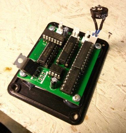
In this case, the display is up on the wall of the hackspace. I wanted it to be maintainable and hackable by people who aren’t comfortable or experienced with SMD. That’s why it also has DIL sockets rather than just soldering the ICs directly into the board. If one of them fails for some reason, someone can just yank it out and put a new one in.
I’ve been using 2x 7492 counters, 2×7485 comparators with a 555 as the clock source since the 80’s!
I saw the original circuit in an Elektor summer circuits.
The big old lunar lander simulator I built that used old car speedometers for instrument displays used 3 of these to drive motors coupled to the cable drives.
It is the simplest digital PWM known to human kind!
what about two schmitt trigger inverter gates and a bunch of resistors/capacitors? you can build 3 independent pwm generators out of a single chip with 6 gates such as the CD40106.
it’s easy, cheap, you can put one together in a few minutes
if you use 7490’s then you can have 0-99 in 1% increments
but hey, whatever you have on hand at the time will do
…Or you can do PWM the old-fashioned way. Get a sawtooth wave generator (easy to do with an NE555) and use a comparator to compare this signal with the input voltage. PWM with only 2 8-pin ICs!
Or the 2 comparators on a LM393, plus a few passives. Only one 8 pin IC.
Yeah, I think this kind of topology is fairly common for hobbyist class-D amplifier designs, so it shouldn’t be too hard to find an example circuit that can be modified.
140 Hz is a bit slow for a small light source. You’ll get annoying flickering.