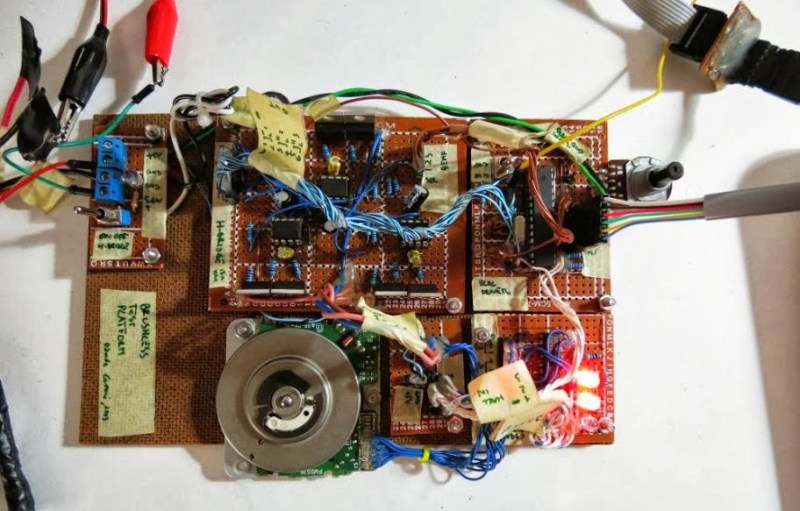
[Davide Gironi] shows us how to implement a sensorless brushless DC motor controller (sensorless BLDC) using an ATmega8 microcontroller. In order to control a BLDC motor you need to know its rotational sequence position and speed so you can calculate and apply the correct current phase sequence to the motor windings at just the right time.
Simply said, sensorless BLDC means you’re not using a purpose built sensor to determine the motor’s position and speed, however, you are sensing the motor’s sequence position using the back EMF signal coming from one of motor’s coils that is not currently receiving power. When this back EMF signal crosses zero voltage a microcontroller can calculate the rotational speed and when to switch to the next power sequence. This technique is not good for position control motors but is great for continuous motors like computer fans and drives were the slightly reduced wiring costs make this type of BLDC control favored.
If you want to build a BLDC controller we recommend starting with [Davide’s] last project on sensor controlled BLDC motors. You can also checkout these interactive demonstrations for more understanding on the different BLDC configurations.
Follow along after the break to watch the video demonstration of [Davide’s] sensorless BLDC controller controlling a motor from CD-ROM drive.


Repost?
http://hackaday.com/2013/09/21/building-a-brushless-motor-controller-around-an-atmega-chip/
And how is that a CD-ROM motor?
Agree on both. Repost and Floppy-drive motor.
Not a repost. Same board, but the motor is sensorless now. The earlier version used a Hall effect sensor.
I’m pretty sure I saw both the sensored *and* sensorless versions posted here.
it’s a floppy, my mistake. it was in my junk box of motors… and i just suppose it was from a cdrom.
the other version is sensored, board is the same but this one is sensorless.
What’s the configuration of that motor, BTW? CD/DVD-ROM ones are usually 9 cog-12 pole, but I haven’t delved into a couple of 5.25″ floppy ones I have yet. What should I expect as far as configuration?
This is clever, and the guy sure knows his onions, so respect there. But why not just use an ESC that you can buy from Hobby King and other places for about 5 quid? Just feed it power and a PWM signal and you’re done. Most of them even have regulators to drive your other circuitry.
Right. And instead of playing sports, you can just turn on the TV and watch somebody else do it.
+1 Trui spoken like a truE hacker! Having built ESC yourself would make you appreciate the engineering that went into that “5 quid” part so much more.
Those cheap ESCs from Hobby King don’t use MOSFET drivers, and as such generate quite a fair bit of heat, with a resulting loss in efficiency.
Looks like they do use MOSFET drivers. Some even claim “high efficiency, all N-channel MOSFET design” in the description.
However they still like to self destruct when being abused, since they have no safety margins ;-)
I’m not sure “self-destructs when abused” counts as much of a mark against something. Having typed that single sentence, you’re fully equipped to run Hobbyking ESCs in all your projects without a single issue. Simply put in your own safety margin by selecting an item with a bit of headroom.
I don’t complain when a 24v supply burns up a 19v laptop, or when a bare MOSFET rated for 1 amp smokes under a 2-amp load. I’m assuming you don’t, either. If you have a 40 amp draw, purchase a controller rated for that times whatever margin you think the manufacturer should have built in. Done!
If you want to pay more, of course you can get hobby ESCs with MOSFET drivers. But you need to pay a heck of a lot more than 5 quid. The MOSFETS in the vast majority of RC ESCs below 30 amps are driven *directly* from the MCU pin.
What do you think they use then? I don’t remember what my 30A escs use, but in the smaller ones IRF8732 is popular, which the datasheet says is a MOSFET. Obviously they do generate some heat but it can be minimalised in various ways (in software and hardware)
They don’t use MOSFET drivers? What are they, tube driven? Relay-actuated? Bipolar transistors (except there’s no cost advantage there, so please explain why that would be likely).
No MOSFET drivers means no MOSFET drivers. They are connected *directly* to the MCU pin. If you don’t understand the difference, go do some reading.
You can’t be serious about this, first, the MCU would have to be happy running at 11.1V logic, second, atmega8 pins can give something on the order of 100mA. I don’t know anyone flying anything powered lower than 6A, but all the 6A rated ESCs from Hobby King do use regular FETs. Here’s the back of a $6.50 Hobby King ESC with some IRF034 mosfets: http://0x.ca/sim/esc/HK_HK-SS10A/img_20130617_181727.jpg
FYI: Atmega8a datasheet p. 244, Absolute Maximum Ratings:
DC Current per I/O Pin 40.0 mA <– Not 100mA as you claimed!
Stresses beyond those listed under "Absolute Maximum Ratings"
may cause permanent damage to the device.
FYI: your picture link to IRF7811 MOSFET in SOIC8, not a IRF034 in
TO3!!! IRF7811 has gate capacitance of 1800pF. The FDS6675 PMOS has
3000pF. They use them for the H-bridge.
With crappy bipolar buffer which is probably what they use , you can
barely do +/- 200mA drive which is under-rated for these type of loads.
Aha, I understood “MOSFET drivers” to be a MOSFET-based driving stage for the motor. If you had said “gate drivers” it would have been obvious.
r4k is saying that the cheap ESCs hook the MOSFET gates directly to a microcontroller I/O pin, he is not suggesting that the motor is being powered directly by a microcontroller. A MOSFET gate driver is often used between a microcontroller and MOSFET to provide more current and/or higher voltage to the MOSFET gate.
When switching a MOSFET from on-to-off, (or vice-versa), the MOSFET goes through a higher resistance state that generates more heat than it would when the MOSFET is completely on. Higher gate drive currents allow the MOSFET to be switched on or off faster, which reduces the heating due to switching. Cheap ESC switch at lower frequencies (often around 1kHz) to avoid over-heating due to the low gate drive current. A 1kHz produces and audible noise. Higher end ESC use > 20kHz switching frequency which is not in the audible hearing range of humans.
There are thousands of different of MOSFET gate drivers available on Digikey under the section “PMIC – MOSFET, Bridge Drivers – External Switch”
Each gate driver provides slightly different features. The Fairchild FAN7842 is an example of a high-side and low-side half-bridge gate driver. It allows N-type MOSFETs (NMOS) to be used on the highside instead of the less effective PMOS FETs. Its also prevents both the high-side and low-side FETs from being turned on at the same time (which is usually a bad thing).
http://www.fairchildsemi.com/ds/FA/FAN7842.pdf
Actually you can do quite precise movements with sensorless BLDC motors similarly as with stepper motors, but BLDCs have other tremendous advantages too.
First off they can go really really fast, or slow: a standard RC hobbies 14-pole 3-phase motor can do 18k RPM or more with an atmega8-based controller (most of those used in RC hobbies are atemga8-based and can be reflashed with custom code), but it can also maintain a given position or work as a passive encoder with a resolution of 3x the number of poles. I.e. a 14-pole motor can track the position with up to 360 / 42 degrees resolution. They’re even used for camera stabilisation gimbals in RC hobbies.
Secondly they can work as dynamos by driving the FETs the right way. This means that, for acrobatic flying, you can reverse the direction of a spinning propeller with almost no energy — the eneregy generated when the motor is braking can be used to immediately re-spin it in the other direction. All this in a fraction of a second at 10k RPM.
Then there are a few interesting electrical tricks to reduce energy use or make things run cooler in RC applications.
This is interesting – never came across a recuperating RC ESC before (but never knew to look for one either). Where does the energy go to? You would have to strap a pretty large capacitor to ESC for this to work, no? Also, I would think resistance of air the would probably kill whatever momentum is left in a light plastic prop before you can extract any useful energy from it. Interesting as a general principal (and I’m sure used in Segway exactly that way) but hard to see its practical application in an RC plane. But if you know of one, please point me in the right direction, I am very intrigued!
IIRC the SimonK firmware, if active braking is enabled, will generate current when braking, including on the cheap HK ESCs. But then I haven’t thought of whether the voltage is right to charge the battery or get stored somewhere else…
I’ve thought of whether the drag would kill the benefits, and I think it won’t. I mean there may be very little energy in a small prop but the current you’re consuming will be reduced by that little amount and not be wasted so the direction change should sitll be “free”. In either case with a 10″ plastic prop abruptly braking to zero is enough of an impulse to break a too thin wooden quadcopter arm.
As for practical use a few people are recently using quadcopters to fly “3d” (i.e. like acrobatic helis) by reversing the spin direction really quickly and you couldn’t do it without active braking (vimeo.com/groups/mwc/videos/75697349)
That’s not how I understand active braking. Active braking may actually take more energy rather than generate it from the momentum of the prop. As far as my understanding goes, it’s a reverse of accelerating – you want your phase shifted back (time of the shift dynamically linked to the RPMs of course) from the point of the max magnetic attraction betwen a pole and the matching cog. So instead of helping the rotation along, each successive step pulls back a little. No current is generated, you still have to energize winding, just in a slightly different order.
You might be right there, I’m not sure if “active” was the right word.
In any case I just asked SimonK about that and he says technically at full throttle the energy will dissipate through the different electrical elements, but at less than that while the FETs are still pulsed by the PWM, “the flyback pushes through the body diodes and raises the input voltage, which typically charges the battery”.
@Andrew – “Regenerative” is the word you were looking for I think.
Or dynamic braking, that’s how it is termed in the servo world.
We call this back EMF…
Did I see the word “simple” somewhere in there? Great job, Davide, but nothing about BLDCs is simple, at least not in the sensorless version anyway, I’d just call it “DIY ESC” or something like that and remove “simple” so as not to confuse people :)
thank you. i should say, “simpler” than SimonK and other open source ESC running on ATmega, and not optimized as those :P
Why not try try comparators with clamping diodes instead of simple resistor dividers?
Resistor dividers tend to perform very poorly at low speeds, comparators make the BEMF sensing way more sensitive, theoretically they even allow position sensing without moving the rotor ;-)
Holy crap, and I have trouble getting cheap steppers to do my bidding on arduinos….
Inpressive stuff.
Theoretically it should be possible to drive a brushless motor with an AC source and 2 capacitors (to introduce the appropriate phase shifts). In this case the motor will turn synchronously and proportionally to the AC frequency. I have been wanting to try this for some time now – I wonder if anyone else has had a crack at it?
A stepper motor can also be made to spin synchronously using the same method:
http://archive.is/6bKNK
In fact, it ought to be possible to only connect one phase up to an AC source like a transformed down mains to get the motor to turn synchronously. The principal can be demonstrated easily enough (I have at least done that) by placing a few magnets around the circumference of an axled disk and placing an AC powered electromagnet such that the magnets sweep across the face of the iron core in close proximity. Give the disk a tweak and it will spin synchronously with the AC frequency.
Controlling RPMs using AC would be a bit.. I mean, difficult. But if you only want to spin it up, then AC sounds like an interesting way of doing it. Although I’m not so sure it will be fast. I think 300RPMs is all you can get from a 60Hz AC (stepped down of course) source on a 12 pole – 9 cog motor. If you just want to spin it real fast, there are other ways to do it. See an opAmp/MOSFET circuit in this message http://elabz.com/forums/post-your-projects/laser-scanning-display-project/#msg269 (circuit not mine, just can’t find the source in a hurry) . Needs a wye configuration, not star as this BLDC though but boy, does it fly! I clocked it at 12,500RPM and it kept going, I just maxed out what I was using for a tachometer. At some point I got scared of losing body parts if the HDD platter would decide to shatter or otherwise separate from the spindle, so I turned it off. But yeah, there are analog way of spinning that motor, that’s for sure.
Controlling RPMs may not be as difficult as you think – all you need is a frequency generator and an amplifier – but hey, if you were to be building those from *scratch* it would be no simpler than build an ESC I suppose.
My suggestion of using the mains was merely a means of demonstrating the principle if someone wanted an easy way to “play” with the idea, but in fact my own application would be 750 RPM so much slower than the way these motors are generally used and therein may lie the rub. My interest in this side of things stems from the fact that *synchronous* motors are now-a-days hard to find and very expensive, whereas RC brushless motors are comparatively cheap and plentiful. Stepper motors can be used for this purpose but suffer from resonance problems in coming up to speed and 750 RPM is actually very fast for a stepper (ramping is necessary because of the comparatively low torque at higher speeds).
The advantage of an analogue signal (in fact a sine wave) is it also prevents “cogging” and some applications (namely my own ;-)) requires just that.
Interestingly your link is to a not-so-dissimilar application to my own – it’s a pity that video has been taken down.
Yes that is a clever circuit, if I am not very much mistaken he has used 2 of the 3 coils as a tacho and is just driving one of the coils as I previously mentioned as a possibility. Similarly that “tacho” output could be provided by an external source which would cause the motor to “lock” to that frequency which is necessary for my purposes.
Did you ever finish that project? (and yes spinning mirrors around at those speeds requires great nerve ;-))
That spin-up circuit uses two of the coils as differential inputs of the opamp and its output drives only one remaining coil. Because it only drives one coil, it has a huge downside – it needs an initial push in the direction you want it to go ’cause it can just as easily go in the opposite direction. It is direction agnostic, so to speak. The “tach” output works like a champ and I was able to control RPMs pretty nicely with PWM using the tach output. It also ramps itself up very well, as long as you provide the initial RMPs so there’s at least some voltage coming out of those sensor coils. But the initial push thing was a deal breaker for me – I cannot afford to touch those mirrors, and they are awkward to spin anyway. Also, if you start adding circuitry for ensuring direction, the complexity goes way up, almost right up to a full ESC.
I haven’t finished it yet – mirror holder is a critical piece and I’ve done 4 different versions (2 of those were 3D printed), still could not get it done to the accuracy I needed (with mirrors attached). Different story of course. I might eventually submit it for another “Fail of the week”, we’ll see. LOL “Fail of the week” seems to be the standard way my projects are making to Hackaday these days ….
Yes having to give the rotating part a “tweak” is a normal characteristic of this type of “synchronous motor” – a similar “hack” is to use a bicycle dynamo as a motor – it also needs a “tweak” to get it going and in the right direction – that’s not such a big deal for me but a common solution to that problem is to use a second simple brushed motor to get it started and then disconnect it. It adds some complexity to the mechanical side of things but not much really.
I wonder if there isn’t a simpler solution to that problem for the brushless though. Do you really need 2 coils for tacho? If you can use just the one you could use the freed up coil as a second driver coil connected to the same drive signal via a capacitor which will give it the phase shift necessary for auto start and correct direction.
I have sympathy for you as the mirror mounting is such a critical factor and at these speeds is a significant engineering problem indeed. I have successfully made accurate mirror drums by building a CNC machine to accurately cut the parts – but at much slower speeds that you envisage – I also don’t have the mirrors at a successively increasing angle – they are all in the same plane and I use a second mirror drum to create the vertical scanning. Good luck with it and even as a “fail of the week” I would be interested in seeing the outcome.
This is too messy, One can basically do the same thing using the DRV11873 Evaluation Module from Texas Instruments (only $25) and an Arduino or IOIO board microcontroller as shown here:
http://youtu.be/BehC_sgthc8
Ultrafast BLDC driver (space vector modulation).
The system is able to commutate 50.000 times per sec.
https://www.youtube.com/watch?v=ouS-8NtM-28
How does his code actually work? I don’t see the comparator interrupt nor use of the fast PWM mode. Is he really just polling the comparator state in the timer overflow irq? How is the speed setting achieved?
Yes, i do not use any compartor interrupt, that’s one of the reason why i call this a “simple” sensorless brushless motor driver. BEMF is been read using ADC input, the speed can not be so high, ACD need at least 13 cycles to read. Anyway, running the micro at 16Mhz the motor spin at almost 3500rpm. Further information and the code behind the project, can be found in the link of the blogpost.
Thanks for the explanation