

It’s time once again for another part in 3D Printering’s series of Making A Thing. Last week was a short tutorial on the beginnings of making a thing in AutoCAD. This is an extremely complex software package, and in a desire to make things short and sweet, I broke this AutoCAD tutorial into two parts.
Since we already covered the 2D design portion of AutoCAD, part II of this tutorial is going to turn our 2D part into a three-dimensional object. Check out the rest of the tutorial below.
Our Thing
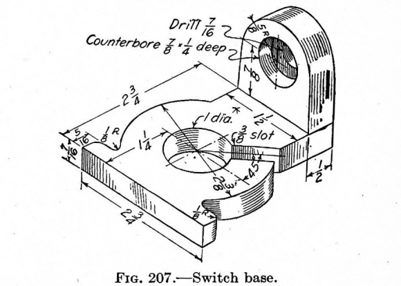
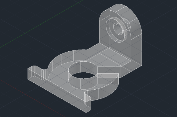
Just like all of these Making a Thing tutorials, we’re using this object pulled out of a nearly 100-year-old textbook on drawing and drafting. We already have a 2D projection of this part, from the previous AutoCAD tutorial, so let’s just dig right in.
Views and Presspull
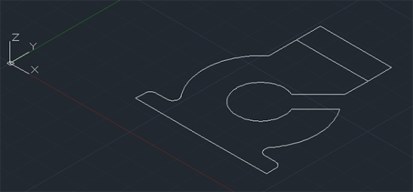 In the last installment of this AutoCAD tutorial, we only used the ‘top’ projection. This is great if you’re working in 2D, but making a 3D object is nearly impossible. The first thing we need to do is change to an isometric projection in AutoCAD. To do this, just click on the ‘view’ tab and change the view to SE Isometric. You’ll end up with something that looks like the picture to the left.
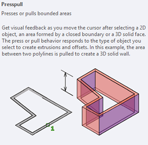
With being able to see the Z axis sorted out, the first order of business is making a 2D object 3D. You might think the command we want to use here is extrude. You’d be terribly wrong, though. The command we want to use is called presspull.
Extrude is an AutoCAD command that pulls the highlighted objects (in our case, the lines making up our part) through the Z axis. It doesn’t make your lines a solid, though, so unless you’re designing single-thickness vases to print on your RepRap, there isn’t much use for extrude.
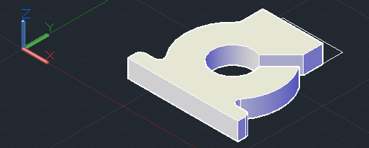
By selecting the presspull command from the ‘solid’ menu in AutoCAD, we can click on the object we want to pull up into the Z axis and make them solid. If you’re following along with this tutorial by copying all these steps, highlight the main part of our ‘thing’, type in presspull, and type in the height you want to pull it up to. In our case, we want this part of our ‘thing’ to be 7/16″ thick, or 0.4375 in decimal inches.
Editing Solids
You’ll notice our ‘thing’ is missing something – the flange on top with the drilled hole. Not to worry, because by playing with the box and cylinder solids we can add that part in. Here’s our process in handy animated .gif format, complete with a textual description of how to do it.
Switch to the NE Isometric view. From the Home tab, select box. This is a tool that allows us to draw a box in three dimensions, by selecting two points on the X and Y axes, and extruding it up through the Z axis.
From the 100-year-old drawing we’re working off of, the top of our box should be 7/16″ tall for the base, then another 7/8″ tall to get to the midpoint of the cylinder we’re going to put on. That adds up to 1.3125 decimal inches, so click one corner of our 2D box, click the opposite corner, and type in 1.3125.
Now we have a bit of a challenge. We need to add the ‘dome’ on our part. This is easily made with the cylinder tool, but we need to make sure it’s aligned on the center of the edge of the box we just made. If you’re following along with this tutorial, you’ve already experienced some of the ‘snap-to’ effects, but nothing that’s a midpoint yet.
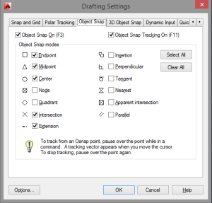
OSNAP. Yep, the command you want to type in is called osnap. That joke gets really, really old after the first week of a drafting class, by the way.
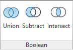
Osnap enables different snap-tos, allowing you to draw something from the midpoint, endpoint, and center. By default midpoint isn’t selected. Click that check box and get hit OK. Draw your cylinder, then from the solid tab, click Union, select both the box and the cylinder and hit enter.
We’re nearly done here. All that’s left to do are the drilled hole through this flange we just created and the counter bore. First we’ll work on the drill that’s 7/16″ in diameter. Not radius, diameter.
Using your new-found osnap skills, draw a cylinder that is 0.21875 decimal inches in diameter. Pull that through our flange and subtract it, just like we unionized the box and cylinder above. The counter bore is left as an exercise to the reader because It’s the exact same process.
Wrapping things up
Since our goal is to design a part for a 3D printer, we’ll need to make an STL file. This is done with the export command. It’s a simple process, but there is one catch: you must select all the objects in a part before saving. Right now, our ‘thing’ is made of two parts – the weird circle thing with a slot, and the dome thing with a hole and counter bore. We could export both these parts together, but that’s rather inelegant. Select Union, click both parts, and hit enter. Then export to .STL.
Will you look at that. We made a thing. You also just learned AutoCAD and the Escape key on your keyboard is crying.
Compared to the previous tutorial of making a thing with OpenSCAD, designing a 3D printable object with AutoCAD isn’t more difficult, it’s just different. Next week, sometime after Christmas, we’ll check out some more 3D design software and make our ‘thing’ once again. If you have any suggestions on what software I should feature, drop a note in the comments. I lost the Post-It that had all the softwares I was planning to use.


How about Solidworks or Inventor, they are both meant for 3D moddeling. 3D CAD in AutoCAD is a pain
Yeah, I really have to agree here. AutoCAD is awesome for quickly hammering out a good 2D draft. (Granted, LibreCAD does like 80% to 90% of what AutoCAD offers on that front.) But 3D…
I mean, it works and there are some really neat tools to be found, but it’s neither as quick as Rhino nor as robust as any constraint-based parametric CAD package, like SolidWorks, NX, or even FreeCAD. Oh sure, Autodesk ostensibly added parametric features to AutoCAD, but they’re clunky and incongruent — individual features can be parameterized, but you don’t have a feature list to refer back to for making changes afterwards.
nonsense, the learning curve might be a pain but once you orient yourself those programs don’t match cad for precision. Build in CAD, animate in Max, add mechanical properties in ProE or SW.
I vote for a feature-based solid modeler as the next tutorial.
SolidWorks is probably the single most widely used example out there. (Maybe Pro/E if not SolidWorks.) But, nice as those programs are, those are huge and expensive programs.
Perhaps FreeCAD would thus be the best for a tutorial like this. It’s free software (as in speech and as in beer), and while it’s still really rough around the edges, I’ve found it works quite okay once you figure out the UI. Certainly plenty well enough for any hobbyist.
+1 for FreeCAD!
Another good tutorial would be nice for this, I have not quite grasped the UI yet, but it seems well suited for my uses.
+1 for FreeCAD. Being able to experiment and learn with a free tool greatly expands the audience and has a higher chance of getting people to follow along with the tutorial.
Thanks for the great tutorials.
Once again, excellent write-up.
I’d really like to see an article or two on calibration and tweaks to improve print quality.
I know that every machine is different, so it isn’t really feasible to cover all of them, but maybe some good calibration objects, recommended slicers, etc.
I’ve gotten my Prusa Mendel working, but the print quality is far from perfect, and there’s so much information I don’t even know where to begin (100+ page long forum threads, etc).
While I appreciate the work you put in an autocad-based tutorial, it is priced outside the hobbyist range and thus of little practical value. Maybe you could extend the tutorial series to also cover the free Freecad and/or the free-as-in-beer DesignSpark Mechanical. That would be greatly appreciated.
These tutorials are excellent. I think it is a great idea to have them as a reference for beginners getting into CAD, 3D printing, and modeling.
I have used several different programs for making things in 3D, including: Alibre, SolidWorks, Inventor, Sketchup, and Autocad. While I started with Alibre and SolidWorks, I migrated to Sketchup once I was out of school since it was free and from my perspective, easier to just crank out some ideas quickly. While it lacks many of the great features other programs like SolidWorks have, I think there is something to be said about its simplistic and seemingly efficient mechanics.
I have recently built my own CNC and in my quest to find the perfect 3D modeling companion, I did look briefly at OpenSCAD. I was turned off by the fact that everything was coded, especially since I initially learned with a completely different methodology. However, looking back and comparing OpenSCAD to AutoCAD, I am shocked at how much more simple OpenSCAD was. Perhaps it is just the part being made, but I think OpenSCAD gets the win here.
Good Job on the tutorials.
I am a long time HaD reader and I remember doing this drawing in high school. We had a very good drafting department where I pushed the pencil for a year and a half and then moved onto using AutoCAD2K for two and a half years until I graduated 7 years ago.
After high school I picked up on Google Sketchup and PlasmaCAM. This also helped prepare me for where I work; even though I was forced into my job – My father owns the company – for now :). We use Signlab, which is made by CADlink. It’s very similar to AutoCad except it only works in 2D. It’s used to make graphics for just about anything from vehicle wraps to backlit signs, labels, and more. One nice thing is that I can export from either Signlab or AutoCAD and import to the other with dxf.
One of our customers builds concession trailers. He was showing me one of his layouts for a new trailer and I noticed he was using AutoCad. I told him I know how to turn his 2D drawings into 3D (since he did not know how) that he could then show to his customers what the trailer would look like before it was built.
A couple years ago he was asked by another trailer company, that he was already building car haulers for, to build a trailer, that looked like their car haulers, but would house a portable jumbo tron that popped out of the top. ( http://www.youtube.com/watch?v=lIBiLZRvCkE ). Sounded simple enough so he said he could build it and asked me if I would help him design some of it so that there wasn’t going to be much material waste with trial and error. Thats when I got AutoCAD2008. The first trailer was built and the rest is history. These two trailer companies have sinced merged and continuing to make bigger and better trailers.
I have since updated to AutoCAD2012 and it has been invaluable to us since we also use it for engineered drawings that we need to have for certain signs. I still do all of their drawings and their graphics.
osnap never gets old
+1 for a FreeCad tutorial. It seems competent, but I got stuck on some bugs that felt like showstoppers. Would be interesting to see how it _should_ be used!
There is no need to use AutoCAD. It is too expensive. Use free software and be calm!
There is no need for AutoCAD. Also it is too expensive. Use free software and be calm.
I’m +1 for Rhino 3D
It is a little pricey, but I absolutely love how it works!
Can also use RhinoCAM to machine directly from Rhino, although I have not yet prodded to see if a 3D print can be made the same way.
Seriously? This guy made a fantastic tutorial and a bunch of people just shit on it because it’s an AutoCAD tutorial (a common drafting program)? Students get it for free. I thoroughly appreciated the tutorial, and use AutoCAD to draw parts. I’d love use Free software, but so far AutoCAD has been the least painful tool I’ve tried.
AutoCad is the carpenter’s hammer while these other programs are either pre-assembled or pre-fabbed homes. Only the true craftsman sticks with time tested methods.
Just a note… presspull command is not available in Autocad 2006 only 2007 and on.