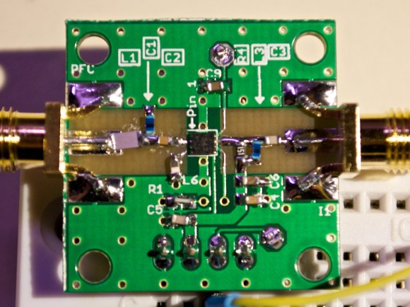
[Will] recently tipped us about a 400MHz Low Noise Amplifier (LNA) module he made. His detailed write-up starts by explaining the theory behind an amplifying chain. Assuming a 50 Ohm antenna system receives a -70dBm signal, the total peak to peak voltage would be less than 200uV (.0002 volts). If the first amplifying stage doesn’t consist of an LNA, then the added noise would later be amplified by the other elements of your system.
[Will] then detailed how he picked his LNA on Digikey, mainly by looking for one that had a less than 1dB Noise Figure. His final choice was the Sky65047: a small budget-priced 0.4-3.0GHz low noise amplifier with a theoretical gain of 20dB at 400MHz. He made the PCB you can see in the picture above, removing the soldermask on the signal path in order to lower the permitivity. Because of a few mistakes present in the application note, it took [Will] quite a while to get his platform up and running with a 20dB gain but a 4.5dB NF. He also measured the input return loss using a directional coupler, which ended up being quite close to the datasheet’s 14dB number.


Sorry the wording on this post is making me cringe. A return loss of 14dB would be terrible. I would imply that more power is returning from the amplifier then you are putting in, by more the n 10 times.
However it seems it is how the datasheet presented it: http://www.skyworksinc.com/uploads/documents/201084D.pdf (page 3)
RF engineers often say ‘a return loss of n dB’, while they actually mean ‘-n dB’. In theory a return loss of >0dB is possible with an active component.
I know, it drives me nuts when people do that, specifically because it is possible to reflect more RF energy then was directed into they system.
Return loss is the loss from a full reflected signal. It is always given as a positive number.
No, 14 dB is correct. It’s a return “loss”‘ meaning your returned signal has “lost” 14 dB. It would have a return gain of -14 dB, but no one uses that terminology. RF engineers know what you are talking about when you even say a return loss of -14 dB, which is incorrect, but they got that from reading 20*LOG10(|s11|).
Return LOSS, not return gain. RL of 14 dB is beautiful; it’s below a 1.5:1 SWR. Return loss means the ratio of signal reflected back due to impedance mismatch.
I’ve used this same amp chip at 900 MHz; it does make a nice LNA.
This is where valve would be more suitable.
Show me a valve amp that can achieve < 1dB noise figure. Thermionic noise limits you.
But it will definitely sound warmer, with a full rich tone that is forward and crisp on the aural palate without being overly fatiguing.
just use this http://ava.upuaut.net/store/index.php?route=product/product&path=72_73&product_id=82
that would have been less fun…
Hittite HMC616LP3 plus the 120728 evaluation board would have also been a good solution.
At $227 it should work well…
Out of curiosity, what’s with all the small holes drilled in the ground plane?
It’s called ground plane stitching – it reduces resistance to ground. Usually there is a solid ground plane on the back of the board. If you omit the ground stitching the bypass capacitors and other items tied to ground will perform less than optimally.
Looks like he had to swap C1 and L1.
No point in worrying too much about the noise figure of an amp this broadband, since it will pick up RF from anything and everything…
Very true. I was surprised to see that. Desensitization and harmonics from strong out-of-band signals are a major concern. I’ll likely need to build a pre-selection filter.
Is it just me or is that solder purple? Very pretty
I wish! I have a fluorescent light at my workstation with a plant bulb. It casts a purple light when I white balance to the rest of the light in the room.