[Afonso] picked up a cheap energy use monitor a few years back. He really like the data it displays about his home’s electricity, using a sensor to gather this info and a display that communicates with it wirelessly. But there is no option to log or dump the data. He set out to reverse engineer the wireless protocol in order to extend the use of the system. As the name of this column implies, he failed to get this working.
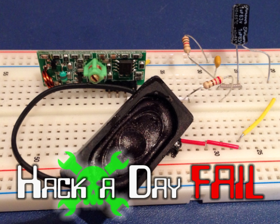
The hardware above is a 433Mhz transceiver that he rigged up as test hardware. It sounds like he’s assuming the monitor works on this band, which could have been his first misstep (we really don’t know). The speaker is there to give audible confirmation that he’s receiving something from the transmitter. This is where things start to get pretty weird. White noise was coming from the speaker, but when he stepped away from the bench it stopped. He was able to measure a regular pattern to the noise, and proceeded to place the speaker next to his computer MIC so that he could record a sample for further analysis.
Fail of the Week always aims to be a positive experience. In this case we’d like to have a conversation about the process itself. We agree that connecting a speaker (or headphones) should help get your foot in the door because your ear will recognize a rhythmic pattern when it is received. But with this noise, measuring the timing and recording a sample we’re not so sure about. Given the situation, how would you have soldiered on for the best chance at successfully sniffing out the communication scheme used by this hardware? Leave a comment below!
 Fail of the Week is a Hackaday column which runs every Wednesday. Help keep the fun rolling by writing about your past failures and sending us a link to the story — or sending in links to fail write ups you find in your Internet travels.


1. Buy a DS1052E
2. Analyze your crap the right way
3. Win!
So constructive and helpful. Thank you so much for taking time out of your day to grace us with your circumspect and edifying words of wisdom.
The hackaday writer asked, “Given the situation, how would you have soldiered on for the best chance at successfully sniffing out the communication scheme used by this hardware? Leave a comment below!”
nigae responded that they would use the right tool for the job. It’s constructive and helpful advice. Maybe not delivered in the most diplomatic way, but fuck it, this is the internet.
“Use an oscilloscope” is a good response to this post.
Poor Hertz, he doesn’t even get the respect to have his initial capitalized anymore. It is MHz!
Given that this is a fail of the week perhaps MegaHurtz is more appropriate.
perhaps the noise is coming from the cell phone in his pocket?
Just what I was thinking.
Connecting the 433 MHz receiver directly to your mic input probably gives a lot clearer picture of the received signal.
Only if the decoded (assuming decoded) signal is in the 0 to 44KHz range.
It usually is. Those 433MHz receivers usually have a (decoded) bandwidth of 10KHz or so anyway.
White noise has no pattern, or it would be pink noise.
In any case, the amp for the speaker is likely picking up signals from his body. I am sure everyone has connected scope probes to themselves and found sine waves of 60Hz 120V or 400+KHz if you are around fluorescent lighting.
My first step would be to get rid of the noise through shielding, filtering, or adding additional stages to the amp so the gain in one amp doesn’t need to be so high.
“White noise has no pattern, or it would be pink noise.”
Can you clarify what you mean? I’m not sure I understand what you’re driving at.
White noise is completely random. Pink noise is made up of specific frequencies.
I assume you want to argue about that? Not really interested and it doesn’t really have much to do with the article anyway.
I don’t really want to argue about it, but I don’t think what you’re saying is accurate. Pink noise is different from white noise in that there is more energy in lower frequencies, which creates equal perceived loudness on all frequencies.
Agree w/loans. White noise is random noise with equal power at any point in the spectrum. Pink noise is random noise that has equal energy in any given octave (falls off at 3db per octave). You won’t hear a pattern in pink noise either, just a tonal difference.
The trouble with these cheap 433MHz receiver modules is that, unless you know what the signal should look like, it’s very difficult to spot the actual transmission in amongst all the noise either side. They have some kind of AGC that makes the signal and the noise before and after appear equally loud. It’s a lot easier to look at unknown signals with something like rtl-sdr because the AGC is less aggressive and you have more control over it, which makes the actual signal stand out more.
If the signal doesn’t stand out above the noise at all, he is likely not even using the correct frequency or method of modulation.
Personally I would have tapped directly into the input of the transmitter to start decoding the data. And then start looking at it wirelessly.
Could be the wrong modulation too, though it’s definitely the correct frequency according to the user manual – but from personal experience, even if the signal is OOK/ASK and on the right frequency and is being received correctly it’s still incredibly hard to see with this kind of setup.
That would pretty much render the device useless, don’t you think? I am fairly certain the signal-to-noise ratio is a design consideration. If what you are saying were completely true, the receiver couldn’t get the signal either.
These modules have a built-in discriminator which converts the signal into digital pulses. So, no, the noise is not transferred along with it or it would be completely useless.
However the discriminator won’t do it’s job if it isn’t using the same frequency, same modulation type, and same keying.
The noise he is hearing is not likely coming from the receiver at all but just interference in the wiring going to the speaker.
Not really. The actual signal is received perfectly clearly, it’s just there’s a bunch of visually similar garbage before and after it. Generally there’s a microcontroller or decoder of some kind attached to the official receiver that can recognize an actual transmission because it’s hardcoded to know (for instance) what length of pulse denotes the start of the transmission, what checksums are used, etc. Unfortunately that information is exactly what Afonso is trying to reverse engineer in the first place.
No. No. That is not at all how these work. The modules are self-contained. All they do is strip off the carrier, and provide a discriminator on the leftover signal. The discriminator is a comparator. A digital one or zero is the output. There is no logic, or microcontroller, or encoder/decoder in these. It simply transmits ones and zeros and doesn’t give a crap what the scheme is.
Some modules do have a tap before the discriminator which allows transmission of an analog signal, but these are the exceptions, not the rule. And besides, that is not at all what he would want to use here.
The output is just a stream of ones and zeros assuming the frequency is correct and the modulation is correct. No noise. That’s what the comparator is for.
This stream of zeros and ones is passed OUT of the module and into a microcontroller or decoder IC where it is then decoded.
Wait… are you suggesting that the modules are also sending out ghost bits (the garbage) and that the microcontroller is supposed to just ignore those extra bits? If so, you had defective modules. Just think for a minute how much more complicated your software would have to be to filter out these ghost bits. I have never once experienced this and if it did, it would make the module absolutely useless. The entire point of a discriminator is to remove the signal from the noise and format it into digital signals. If the noise was also amplified to the point of triggering the discriminator, then it would be absolutely useless.
Yes, I am kind of saying that the modules output “ghost bits” before and after the actual transmission that need to be ignored by the microcontroller, except that they’re not really bits. As you correctly point out, the module simply contains a comparator that outputs either zero or one – it has no concept of “bits” because that would imply the signal is chopped up into discrete intervals and it simply doesn’t work that way. It’s up to the microcontroller to take that digital signal and divide it up into bits and packets, generally through some kind of self-clocking digital coding such as Manchester coding.
Now, of course, ignoring the garbage before and after does make more work for the microcontroller, but it needs to be able to do that anyway because 433 MHz is crowded. There are all kinds of other devices transmitting on the same frequency using the same kind of transmitter and receiver, all of which it sees and has to ignore. (For stuff like remote controls people would traditionally use a dedicated decoder chip like the PT2272 rather than a microcontroller, but it plays the same role.)
The second step is determine if the wireless link is indeed 433Mhz (look it up by its FCC ID) and then whether it is using AM or FM, then ASK, OOK, CW, FSK, PSK modulation…
Without that information, he is shooting in the dark and really going off trying to explore the white noise just pulls him further away from his goal.
Look up the device on the FCC website using the FCC ID and see if you can find the above information. More than likely you will find at least part of it. Then use the process of elimination to determine the rest.
coding, not modulation…
In digital communications, you can call schemes like OOK “modulation”. I assume you come from an analog background, or your education was done by people emphasizing the difference between “putting a signal on a certain frequency with a certain spectral shape” (modulation) and “coding data as constellation points”.
While ASK, PSK, QAM, FSK to a limit etc fit the latter category, they *do* determine the spectral shape. That’s why nowadays you don’t distinguish between modulation and signal representation.
Furthermore, using “coding” is very, very, VERY misleading. Don’t use it for this, really.
You’re automatically confuse people; usually you refer to channel coding or source coding, which is information theory. But even that has a (probabilistic) effect on signal shape – a properly source coded GMFSK will look a lot whiter on an average PSD plot.
Or just call it keying. My strength is digital. I was never very good with analog because I hate math.
However, yes I was taught to view the signal as constellation points.
Step 0 – Read the user guide. Know how the device works. Since the sensor has no actual connection to the line being measured (it measures only current via a clamp-on current transformer), there is no chance of hazardous voltages.
Step 1 – Get the necessary tools. An oscilloscope would have been helpful. The audio input to your computer can function as a crude, low frequency (up to about 15kHz) oscilloscope with the appropriate software. Likely good enough for this project.
Step 2 – Determine the carrier frequency. You have to be able to hear the thing before you can understand it. DON’T assume it’s 433MHz. Look up the FCC ID number – this may provide frequency and modulation. (Umm – since this is from Europe, you’ll have to look up corresponding regulatory agencies.)
The original poster never really got past this point, made too many assumptions, and lacked just about every possible tool to see what he was really working with.
————
Step 3 – Since you have access to the transmitter signal (DAT), probe it and see if you can detect a corresponding signal at your receiver. Lacking that, identify the components used, and find their datasheets. This may suggest what is actually being transmitted, as well as what those other pads are doing (PCLK, TX, RX, REST, etc).
Step 4 – determine modulation. OOK (On-Off Keying) is probably correct. FSK (Frequency Shift Keying) is also possible, though less likely. More complex modulation techniques are required with higher bandwidth data, and costs more money to implement than OOK and FSK. Rule out simpler modulation first.
Step 5 – extract bits from the modulation.
Step 6 – decode the bits. By probing the DAT signal at the transmitter, most of the above steps above could have been skipped.
The only hardware anyone should consider buying for their first DIY RF reverse engineering is a DVB-T dongle compatible with librtlsdr. $20 goes a long way to get your foot in the RF door. You would be surprised how much usefulness you can squeeze out of an rtl-sdr.
Totally agree! All you need is a cheap usb DVB-T dongle along with #SDR software and you can easily sniff the RF waves coming out from the device. Check out my blog for RF decoding http://translate.google.com/translate?sl=el&tl=en&js=n&prev=_t&hl=el&ie=UTF-8&u=http%3A%2F%2Fwww.arduinogr.com%2F2013%2F12%2Frf-signal-decoding.html&act=url
+1. I got quite a way with this (see http://www.mattvenn.net/2013/03/09/gnuradio-demodulate-fsk-received-from-an-rfm12b/) but when I moved back to the energy monitor I realised I didn’t know any of the coding, checksumming, etc. I hadn’t realised that the modules were doing a whole lot more stuff that I thought.
Thats when you start giving it known inputs. Reverse-engineering an energy monitor shouldn’t take more than an afternoon with a dvb-t sdr.
once you know what you’re doing! It took me one whole afternoon to just get an fm receiver working for the first time!
But once you have done it once, it’s easy to keep going! Says I who started with a RTL-SDR thing and an Efergy energy meter, then moved on to reverse engineer other 433MHz (AM ASK) and 27MHz (FM FSK) waves.
With the energy meter, one f those cheap transmit/receive pairs (like in the OP picture) and an Arduino worked well enough – except the transmitter only sent the -sum- of my three phases. And the clamps weren’t linear.
So that was a bit of a fail. I ended up reselling the Efergy and its clamps, buying new linear clamps, and using the RF pair to send/receive data through two arduinos.
(Why did I want that? Because of seeing what draw there was on each phase, so I would know where it would be handy to plug in new, energy-consuming equipment. )
The short of it being that yes, I saw radio as black magic, but I did learn a lot about the hows and whys of how it works in practice from experimenting. Turn fails into experience, that’s what it’s about.
(I used SDRsharp and Sigmira in Windows to look at waves, and rtl_fm and gqrx in Linux. And Audacity under both, to look at saved radio bursts.)
well, for one thing, 433MHz is actually a band spanning quite a bit with quire a few channels, depending the transmission mode. His receiver can be simply out of tune. Or use a different kind of modulation. Or the data rate is so high that you will not be able to hear it.
What is see is that the radio is a small module with supply pins and a DAT pin. That is where data comes from, that is where he should start. If wireless is not important for now, he can start from there and see the protocol and get the data.
I am also willing to bet that TX and RX are some usart pins, but he may need to send some commands to enable it first…
or, just use the current sensor from the transmitter and make his own, plenty of arudino energy meters out there.
Ok, it would help if someone who says “this is a no brainer” had actually any background in rf communications.
He tries to use an integrated transceiver system to analyze a system that’s probably totally different. Ok, you can detect OOK (if that really is what the thing is transmitting), because on and off are basically two different amplitudes; however, one would assume that the receiver chip is somewhat selective, probably even has a very distinct pulse shape etc pp. You can’t hear “additive white gaussian noise”, you can hear noise that is white within the audible spectrum. It’s just semantics, but that’s someone with half a wikipedia article of knowledge talking instead of actually reading two more articles.
This is not a fail worth mentioning. It’s like someone standing in front of his car and saying “I can repair this piston thingie, I think it’s called motor. It’s a total no-brainer. I have a similar thing lying at home to plunge my toilet”. No you don’t. And it is no no-brainer unless you are *really* experienced.
And every tinker knows that things are hard at least at first and it is better to understand what you are doing; and if something has so many possibilities to be done like wireless transmission, you should most probably try to read up a little bit on your own hardware before you invest hours upon hours trying to get something running that might not fit the problem *the least*.
Oh my! I like your attitude!
And back to the subject matter…. I’ve noticed it is STILL not Wednesday!
+1, I did the same thing because I knew nothing about RF modules.
I disagree with this position. I think it’s a good FAIL article since a lot of people getting into electronics can relate to it. I think this kind of tinkering and trial and error is a very good approach compared to “learn a bunch things about RF before actually poking at your hardware”. I cam personnaly relate to Afonso and this motivates me to carry on poking at some hardware pieces lying around. And I’m sure Afonso is benifiting from all the helpful comments here.
hackaday please carry on posting these newbie fails.
He should get a £5 logical analyzer like this one: http://www.ebay.co.uk/sch/i.html?_nkw=CY7C68013A+%2B+board+-core&_sacat=0&_odkw=CY7C68013A+%2B+board&LH_BIN=1&_sop=15&_jgr=1&_fcid=192&gbr=1&_osacat=0&LH_PrefLoc=2&_sc=1
works great on a 32bit computer, but needs some hack to work on a 64 bit one (due to driver issues)
I have one of those, but found this better:
http://www.banggood.com/USB-Saleae-24M-8CH-24MHz-8Channel-Logic-Analyzer-Latest-Support-1_1_15-p-74101.html
http://www.ebay.co.uk/sch/i.html?_odkw=CY7C68013A+%2B+board+-core&LH_BIN=1&_sop=15&_jgr=1&gbr=1&_fcid=192&_osacat=0&LH_PrefLoc=2&_sc=1&_trksid=p2045573.m570.l1313.TR0.TRC0.Xsaleae&_nkw=saleae&_sacat=0&_from=R40
(use a better usb cable and it works even better.)
I should say that if you can afford it, go for the official version, it is the software that makes these devices worth while.
Who, Saleae? (http://www.saleae.com/logic)
+1.
Thanks, will give it a try!
Early in the investigation it was observed that audio was present on the output and contained a discernible pattern. To document this pattern for possible further analysis later a simple audio recording was made.
Sounds like a very rational first few steps to me. Observe something and document it… document EVERYTHING… might be valuable later, might not, but not gonna get anywhere till you document it and examine all the facts later. Oddly enough this is also following the techniques used by a few others like Thomas Edison, Nikola Tesla, Galileo, Archimedes, and a long list of many others.
Just because the data collected was likely of low quality and little use does not mean it was Fred Flintstone making a useless effort, yet that seems to be the slant being taken by all here. It wasn’t a mistake. It’s the scientific process being demonstrated.
Gentlemen, I propose what you have here is the simple process used by all the best minds in the world. Observe, document, and later try to understand it for potential use. Publish both the observations and your hypothesis for honest fair and respectful peer review.
Perfectly good points about the scientific approach and all … but we are not talking about uncharted phenomena or bleeding edge research here. Fail here is the lack of knowledge of lack of knowledge :)
IE: The learning process. A highly venerated and observed ritual observed by much more than millions throughout all of history. Labelling such events as failure has a dissuasive influence on progress, but most notably those that hand it down as failure so forget that they themselves started out in diapers and learned the results of that first fistful of dirt transferred to mouth which seemed such a logical answer to hunger at the moment, thus themselves giving a great beginning to the scientific process which has the entirety of its foundation based on failure through seeking success, and success by perseverance throughout repetitive failure.
I totally agree that stuff should be archived – it may come in handy later. And for me, it was a work/temp space to see what different data I had and draw conclusions from that. To begin with, identifying ‘okay, so this part of the packet never changes’, then ‘this is the ID for a particular device’, then ‘this is the value’. In the case of energy meter, it’s handy to have a wattmeter that plugs into a wall outlet and just put the clamp on one of the wires, then see how the wattmeter readings correlate to packet contents.
Then for the advanced course, definitely a logic analyzer or logging oscilloscope; I have one of the cheap USBee clones and it’s good enough for my use. Then poking at data lines inside the project will give even more cool info, either to directly inject (with a transistor or whatnot) or to see how raw data compares to the recorded radio signals.
Uhmm.. I’m drifting off topic. I guess what I mean to say is don’t throw stuff (logged data, notes) away – it may be what suddenly gives you an ‘aha!’ notion and solves the thing.
“Basic Research is what I’m doing when I don’t know what I’m doing. ”
-Wernher von Braun
I hadn’t heard/read that one before. I think I’ll keep it…
All 433 MHz receivers are not created equal, so the one he chose to use may not be capable of tuning or demodulating the signal he’s after. I agree with those who suggested the USB DVB receiver and rtl-sdr software to analyze the RF. An excellent tool at a ridiculously low price. If he’s adventurous, he could even build a demodulator and protocol decoder and run it on his PC.
If he wants access to the baseband signal, perhaps a peek inside the receiver unit would help. Sometimes there is a test point available that will allow you to pick off the demodulated signal — if you’re lucky!
This is a project that I have been meaning to try for a while. From my experience, connecting a speaker to one of these wireless modules and recording the audio (I was staying with my parent’s house for a while and did not have my scope with me) does not yield many results at all, and the best way of getting meaningful data from them is with a scope. I am pretty sure that energy monitor in question uses the frequency expected. Also, I find that connecting an LED and watching it flicker can be useful to see if data is being transmitted, and it can also show if the output of the wireless module is low or high for long periods of time, which the speaker may not. I have very little electronics knowledge so may be mistaken here, but there seems to be some smoothing on the output of those modules. Sadly I can’t think or anything useful to suggest, other than “get a scope”.
I have only briefly read most of the comments here, so forgive me if I am repeating things.
Good luck!
Look up info on a RC circuit, and the theory with it and it should explain everything you need to know about wireless transmission theory and basics. Just remember if you want to learn something, the best way to learn is the way it played out in history. So learning how someone came up with a theory, and someone else invented something, etc shows you the idea, application, and improvements made.
How about a USB TV tuner? They work in that range and if you get into the demod circuit you’ll see the digital transport rather than the carrier itself. Cheap and defined results.
Why not just use an osciliscope on the antenna, or google the spec sheet on the driving chip? Personally I would try reverse engineering the reciever not the transciever. When you see data on a screen or can interact with it, the information has already been formatted, so all you have to do is start from there and work backwards. Its easier to proceed this way, but it is much longer, unless you screw around trying to reverse engineer the middle forever.
I know there’s less elegance and “hack” in it, but why not use the stock receiver and poke at it that way? Let the wireless hardware do its thing and add logging to the receiver. Worst case you end up patching into the LCD driver.
Dat MIC!
Learn from other peoples mistakes ..