No matter how small you make your embedded projects, you still need a way to program the MCU. Standard programming headers can be annoyingly large for those very small projects. [Danny] wrote in to tell us how we can save room on our PCB designs using special spring loaded connectors, rather than large headers.
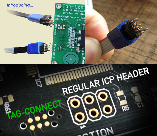
There are so many small embedded development systems, such as the Trinket that still rely on standard headers. Reducing the size of the programming headers and interface headers is an issue that deserves more attention than it currently receives. Based on Tag-Connect, a proprietary connector built around pogo-style pins, your PCB does not actually require any on-board mating connector. The PCB footprint simply has test-pads that connect with the pogo-pins and holes that allow for a rock solid connection. While the Tag-Connect header is a bit expensive (it costs about $34), you only need to buy it once.
It would be great to see even smaller Tag-Connect cables. Do you have a similar solution? What about something even smaller and more compact? Write in to tell us about any ultra-compact connector solutions you have been using!


How about a good ol’ fashioned edge connector?
There are a couple reason. An edge connector can require a non-square PCB and possibly non-basic PCB fab methods. An edge connector is most likely larger as well. The non-locking 6-pin connector is about the size of an 0805 part. You can put it right next to where it needs to be instead of running traces to an edge. However if you need more signals or power, an edge connector is probably the way to go.
not really feasible for smaller boards where this is most commonly used for
I’ve used TAG CONNECT for a long time now. IMHO the problem is their footprint is too small – you can’t route through the pads, you gave to route around them, and you burn as much space as a 6 pin 0.100″ header.
I explain this in more detail here:
http://ludzinc.blogspot.com.au/2013/03/missed-it-by-that-much.html?m=1
Just shrink the pad size down and don’t use the version that has those huge goofy mounting holes, they have one that clips onto the metal pins, so what’s the point in using a 7-hole footprint if 3 works the same? (given that you have access to the backside of the board)
This might sound like an antiquated solution, but what about an edge connector?
For sure it’s a good idea, seriously, 40/50$ for a cable and a connector seems a lot to me. I rather prefer to stay stick to standard conns in case of prototyping.
i have used these for years now and they work well for a product … if you plan on reprogramming it over months than either solder a proper header on to them as the pads will wear out!
the full size locking one is not much smaller than a simple header and if your going that route just go for the low pitch headers … but the small non-locking “production” one works great! never missed a programming due to the connector and never had a “plug” break on me!
Tin the pads and you’ll only be wearing away the solder.
Tinning them made the problem worse as they tend to stick to the probes (that are pointed like a crown) and lift off the PCB
I’ve used the Tag-Connect on the last few designs I’ve done and I think they are amazing. I’ve have both the locking and non-locking cable with an ST-LINKV2 in SWD mode. One thing that isn’t mentioned on any Tag-Connect documentation I’ve seen, is that the tips of the pogo-pins they use have several small spikes on the end. I’ve been able to re-program boards after conformal coating, because these spike poke right through.
Sounds like a job for a 3D printer :)
Agreed on the 3D print aspect. As the post far below says, make a jig and print around it.
If the print head is too large to ‘fill in’ the area, one option would be to print a ‘shell’ and fill with epoxy/HMA (hot glue). Most commercial cables that I’ve deconstructed are using an HMA injected into some sort of casing anyway.
The tag connect is nice and all, but an AVR still requires 6-pins for a AVRISP interface. Or a crowded 2-layer board, connecting all the signals to an AVRISP interface can be a challenge. On a lower pin-count AVR the AVRISP eats up a lot of useful pins.
I was excited when Atmel announced the debugWIRE inteface. It only requires two wires (ground and the reset pin).
Unfortunately, the debugWIRE is not enable by default. You need to change the fuse setting to enable debugWIRE (which requires the AVRISP interface). In my opinion, this cripples much of the advantage of the debugWIRE interface.
AFAIK, there is no source for AVR parts where debugWIRE has been enabled at the factory.
The other problem with debugWIRE for battery-powered devices is that the chip will use more power while it’s enabled.
So you’ll want to disable it for many production devices anyway.
I prefer microcontrollers that can be programmed through the UART port. Only takes 2 pins and GND, and the same port can be used for debug/control afterwards.
You forgot the reset pin. SWD really does only require 2 pins and ground, is much much faster and you can use it for actual debugging (rather than just tracing).
No, I have a software reset that is triggered when a special character is sent. For instance, on NXP LPC, a ‘?’ character forces a jump to the ROM bootloader. In case that doesn’t work, there’s a manual reset switch (or just a bare contact somewhere on the board that I can short with some tweezers).
I have no interest in a ‘real’ debugger. I prefer some printf()s, and maybe a few blinking leds for real time stuff. Speed is usually not a problem. And in the few cases that I’ve written big programs, there’s always been something like an ethernet interface to load programs with.
A huge advantage of printf()-style debugging is that you can also debug remotely. Sometimes I send a customer a debug image, they capture the output log, and e-mail that back to me. This can be very helpful when the customer is on the other side of the world, facing a one-in-a-million problem. It only requires a 3 pin cable with a TTL USB UART on the other side.
Ignorance of SWO is your loss
2nd-ing what F said above.
And one thing. The only “TRUI” I know in the world is the Tim Robot Universitas Indonesia. Is that you?
Programming without breakpoints is a PITA, good luck printf-ing anything that’s not working right.
You could cheaply and easily reproduce this with two pieces of PCB spaced slightly with the pogo and alignment pins soldered onto the back pcb protruding through the front PCB, then just route the pins to a standard connector…
I uses pogo pins in a 2×3 spacing just like the regular ICP header. So I can solder a header onto the development board, or just hold the pogo pins against the pads of the header for mass production.
Like this…
http://www.franksworkshop.com.au/images/pogo_icp.jpg
was about to say.
$33.95 for cable? did i get it right? :D you must be crazy… i will stick with pcb edge connector…
PCB edge is fine if you have the space to spare. For large production runs that edge connector is going to cost you in board area.
for large production runs, you can make your very own debug connector from pogo pins, get exactly the pinout and form factor you want
$6 https://www.tindie.com/products/BBTech/6-pin-pin-header-to-test-probe/
Check out some of the other cool stuff is the “tools” section.
That’s much bigger and doesn’t have the alignment pins, but it is a nice cheaper alternative (and free international shipping!).
A JST-SH-6 connector is my way to go.
That’s brilliant! All the benefits of 1.0mm headers without the hassle: lack of polarizer, annoying tiny THT soldering, easily bendable!
I’ve had good results with a 0.05″ inline header!
Here’s an ISP to ‘micro’ ISP adapter I built, breaking out reset and power injection capabilities. It’s so thin that it easily fits into most board footprints.
http://i.imgur.com/SzSM0J1.jpg
(Sorry, no pictures of the target board I can share)
A 6-pin male header solders to the adapter.
The target board has a matching row of 6 holes.
The adapter is just pressed at an angle to the target board, and makes good contact.
If you need to program a development board over and over, you can just solder a female header onto the target.
We use tag-connects on our production boards – for programming and debug.
I use the for my personal stuff too – I build panelised boards – the cost of buying 45 tag-connect cables to put into a test fixture is a real problem – the pins are on 0.5 mil centers finding tiny pogo pins to make replacement fixtures is hard and is my current project
You could run traces for those signals through the mouse bites to the panel frame to a more convenient pad layout or connector
Are you guys spying on me? My current project uses a K-thermocouple with a interpolated lookup (which you covered on Saturday) and I should have a TagConnect cable on its way to me so I can ditch the pin header I normally use. I may do a couple of boards with both headers to start with.
I built something like this years ago, i just used the standard AVR ISP layout, but replaced the through hole mounting with same size bare copper pads, then i put pogo pins on a board and attached it to a clothes pin.
Since i don’t have any holes this is great for boards that need a clean look on one side.
The bonus is that this solution will also work on unmounted standard ISP headers.
https://www.youtube.com/watch?v=SPft3X8aTJA
That’s a very nice, cheap and non-proprietary solution.
Thanks for sharing! :-D
Cheap, replicable, and (most importantly) gets the job done! Thanks for sharing
I use the pogo pins from the battery connector of old SonyEricsson phone and 5 pads on the PCB.
Works good even on my toner transfer boards.
In a current project I have SPI routed to a flexprint header. If you’re at liberty to add another signal to the header, add reset and you’re good to go. Otherwise a pad next to the reset pull-up and a single pogo pin will do.
tag connect has caught my eye before but I cannot see how the locking version will survive many mating cycles.
These are great. I’ve been using them for several years now and have never had any issues!
One thing worth mentioning is that, if your board has two microcontrollers, you can reuse the same alignment pins if you place the second set of programming pads in the same location but on the back side of your board. The only caveat is that this approach doesn’t work well if you only have access to one side of the board (ex: if your board is secured in an enclosure).
This is great! I didn’t know these existed. This kind of useful tip is what makes me keep reading Hack A Day. Thank you!
Instead of board-edge connectors or pin headers, I came up with my own method for some small battery management boards I made. I put 4 pads along the edge of the board, then used hot glue to mount 4 wires on a plastic paper clip (see the photos below). Those 4 wires are the MISO, MOSI, SCK, and Reset pins. The Vcc and GND go through the programming/calibration tool I made, but you could just as easily use 6 pads instead of 4 to have it all on the edge. To program it, I just clip the tool on to the board and upload my code from the IDE.
Photos:
https://dl.dropboxusercontent.com/u/301235/EV%20Project/programming1.jpg
https://dl.dropboxusercontent.com/u/301235/EV%20Project/programming2.jpg
https://dl.dropboxusercontent.com/u/301235/EV%20Project/programming3.jpg
Neat. I like it.
That is nice and simple. I like it.
isn’t that just a more complicated edge-connector?!
I’ve started using these for a few projexts:
https://www.tindie.com/products/madworm/tiny-avr-isp-pogo-pin-programmig-adapter/
Assembly can be a bit tricky, but after that they work pretty well.
Sorry you had issues building it. I thought I had placed enough “warnings sings” regarding assembly. But you got it working nevertheless.
This is what I use:
http://www.ebay.com/itm/1-5mm-6-position-Spring-Loaded-Pogo-Pin-Adapter-Jtag-/261075193437?pt=PCC_Modems&hash=item3cc94b4e5d
When I first saw the picture I thought it was a modified DB-9 connector. I wonder if a person could do it that way too by using a DB-9 female with rigid pins of some sort on 3 outer pins and pogos plugged into 6 of the inner ones.
why not just use car battery jumper cables, db-9 connectors are gigantic
Does seem like a good project for a 3d printer.I wonder if you vould build a jig to hold the pins and then print the connector around them.
In one of my projects (digital watch with color Nokia LCD, ATmega8A, LiPo Battery with ultra-simple charging method), I used a MicroUSB port for charging and software USB (V-USB). Also I connected the three pins of the MicroUSB port (other than +5V and GND) to SCK, MISO and MOSI. I also made a special ISP to MicroUSB adapter (with the addition of a manually connected RESET pin on-board). In this way, in normal situation, the MicroUSB port acts as a normal port for USB connectivity and charging. But when you connect the special yet simple adapter, it acts as ISP. The only thing is that you still have to connect RESET with a wire to the ISP. But I omitted the ISP port completely without losing its function.
I will write about my projects someday in my new blog (http://me.gheysari.com – don’t click! Nothing’s there yet!).
Actually I’m looking for votes about which of my projects should I post first on my blog. Please help me decide which project is more attractable to post as my first blog post?
1. The aforementioned watch.
2. An Arduino compatible innovative unlimited extendable development board with various modules. The modules connect to the main board or each other with an edge connector. Each module has one edge connectors on each side which are connected together. So you can connect as much modules as you want together instead of stacking them like Arduino shields which is limited. There is also connectors like Arduino on the main board to connect shields or use for experiments. Dual voltage 3.3/5V. Simple software USB connectivity without FTDI. Arduino compatible USBasp bootloader only in 2KB.
3. An infrared sensitive counter
4. A remote controlled vibrating dildo with programmable vibration patterns
5. A touch color LCD development board with ATmega128
6. A recorder/player for 315/433MHz remote controllers which is able to open any car/garage door/etc,
and other projects.
The charger that I design/built uses the SPI to talk to the Nokia LCD. I added the extra reset line and use the same connector for both LCD and ISP. I had the ISP cable connected during my development as it doesn’t interfere with the board in normal operation. LCD only uses MOSI, so don’t have to worry about contention issues and programmer tristates its pins.
That’s also a very good idea! Small and useful. Plus you have 10 pins which gives you 4 extra pins for other things such as UART debugging. The connector is also easy to find, cheap and has good quality.
We just started using these where I work, they’re lovely for manufacturing. We standardized a pinout for jtag and microcontroller programming interfaces on the same connector so as far as manufacturing is concerned, you just push the pins onto the pads, push a button and the device is programmed.
Might not be as cost effective for one offs and homebrew, but I imagine putting some pogopins on a 2mm pitch type connector would get a similar effect.
I used this http://katalog.we-online.de/en/em/653_1xx_124_022 in my Projects.
13 x 6 mm is quite small, but bit enough even for big thumbs.
Good for production and development.
If I were using a SOIC-8 like a tiny85 and didn’t have room for breakouts, I’d just use a SOIC test clip – they’re <$10.
I’ve been using ISPTouch (http://www.daniel-spilker.com/blog/2011/04/25/isptouch-for-avr-microcontrollers).
I search for ” AVX 9188″ on digikey’s site and found it. AVX’s part# is 009188006020062
digikey’s part#: 478-5491-1-ND
That AVX connector looks good. At $1.21 QTY 1, it doesn’t break the bank either even if I stock 10 of them.
cool stuff there
And we have a winner!
this is the exact same concept from the article (paid advertisement?) but in a cleaner package and using slightly-less-proprietary connectors.
This, my friends, THIS is the solution. It’s got everything tag-connect’s got without the single-vendor. You could conceivably implement this with surface mount pogo pins (something like Mill-Max 0910-1-57-20-75-14-11-0, Digikey ED90454CT-ND) and get rid of the AVX connector if that’s a problem.
Great post, thank you very much for the tip!
Nice and professional looking. Seems like you can not use the connector the wrong way either. Could probably be some kind of clamp.
Picaxe programming usually requires a standard stereo headphone socket which makes things simple and easy, but when I’ve soldered boards with SMD Picaxe chips it seems a bit ludicrus to include a large socket that dwarfs the microcontroller in the case of the 8 pin ones.
So I’ve started using my own 2mm pin header arrangement, GND in the center and TX & RX on the outside, it doesn’t matter if I plug the cable in the wrong way round as nothing will happen.
Mill-max makes 0.1″ pitch spring loaded contacts in single or double row.
These looks like a professional alternative of soldering or hot gluing pogo pins trying to make a programming plug for a PCB for the unpopulated header.
You can search for it at digikey: “ED817” for double row, “ED819” for single row.
They are in the less than $30 range, but have 64 or 72 contacts which looks like you can cut/file them down into smaller strips. Digikey also offers to cut them for you for a fee + # of pins.
Reading their 2896 pages of catalog now. By the time I am done, there will be half a dozen newer rev already.
I use a 1mm pitch header with through holes designed to fit snugly. ARM SWD needs only 4 pins. I solder it to either a ribbon cable or flex cable, and then on the other end to the debugger.
I’ve also done one of https://www.digikey.com/product-detail/en/te-connectivity-amp-connectors/2199035-2/A120577CT-ND/5021727 similar to the ISP-Touch thing above, nice thing is that it means you can put the footprint for the standard SMD Cortex 10-pin SWD header down and either use the springloaded pins or solder on the header if you’re going to do debugging for a long time.
Not a fan of the tag-connect myself. If you don’t get the one with the latch then you’re holding the thing down against the board. Not a problem for simple flashing but for debug it’s a no-go. They do have a “retaining clip” that mounts on the bottom of the board and attaches to the through-hole pins but this bends over time and loses its retention force.
In a production environment you should already have a bed of nails to test the board with, and it’s trivial to grab another 6 or 8 pins for JTAG on the fixture.
All in all it’s a nice idea but proprietary and pricey. Was this post an ad?
I’ve been using 1.25mm headers like Molex 53047s: http://www.digikey.com/product-search/en?vendor=0&keywords=53047-05
The unpopulated through-hole connector footprint is on the board wherever is convenient, squeezed down to minimum size (minimum drill size and small annular rings, etc.). I’ve just soldered rainbow wire to the “top” of a connector to form the programming cable (the other end has a programmer-specific connector), and epoxied it for longevity. To program, the exposed pin end is inserted (as if populating the header for real) and momentarily held in place by finger pressure. Of course, for any kind of longterm debugging one can actually populate the header properly and connect to it with the appropriate mating end.
Of course, then I started playing with EFM32s and rendered this mostly moot: on these there is a preloaded serial/USB bootloader that is accessed by driving Vcc on one of its in-circuit programming lines at startup. For production this is way easier than fiddling with any tiny programming cables or one-off pogo jigs.
We have a 1 to 40 pin pogo header clamp available :
https://www.kickstarter.com/projects/1250664710/pcb-quick-connect-clip-40-pin-raspberry-pi-compati?ref=hackaday
This may be of interest to some people here, check it out !
Matt
Search eBay for “pogo clip” to find something similar (disadvantage is that the pads need to be located somewhere close to the edge).