If you’re dealing with RF, you’ll probably have the need to generate a variety of clock signals. Fortunately, [Jason] has applied his knowledge to build a SI5351 library for the Arduino and a breakout board for the chip.
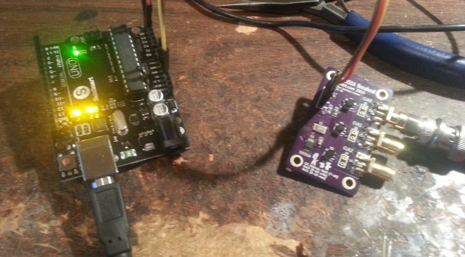
The SI5351 is a programmable clock generator. It can output up to eight unique frequencies at 8 kHz to 133 MHz. This makes it a handy tool for building up RF projects. [Jason]’s breakout board provides 3 isolated clock outputs on SMA connectors. A header connects to an Arduino, which provides power and control over I2C.
If you’re looking for an application, [Jason]’s prototype single-sideband radio shows the chip in action. This radio uses two of the SI5351 clocks: one for the VFO and one for the BFO. This reduces the part count, and could make this design quite cheap.
The Arduino library is available on Github, and you can order a SI5351 breakout board from OSHPark.


If you want a quick play with clock generators and have no patience for shipping delay dig into old pile of broken computers (everyone has one of those, right? .. RIGHT?). Every pc motherboard has one of those, and chips from Pentium2 up to pentium4 era are documented quite well, you can even find softfsb sources somewhere.
@Rasz_pl: The PC mobo clock generators (the metal cans with 4 pins) are fixed frequency. Not very useful for a radio project. The SI Labs chips are can generate any frequency in the working range, by programming it in via I2C signals.
What shocks me more is that the guy has used a $3, hard-to-find part for a BFO – that’s essentially a fixed frequency oscillator, without particular stability requirements, something that is easily built using a few jellybean parts.
?
I dont think you know what Im talking about. There are no fixed 4 pin clock gens on PC motherboards. PC boards need features like dynamic clock switching and spread spectrum.
http://www13.plala.or.jp/setfsb/
The part has spread spectrum if you need.want that.
Spread Spectrum Frequency Deviation SSDEV
Down spread –0.1 — –2.5 %
Center spread ±0.1 — ±1.5 %
It doesn’t have dynamic clock switching as it is *not* a PC motherboard synthesizer nor trying to replace one.
They haven’t used metal can oscillators since the CGA/EGA days probably for cost reasons.
For a while, the motherboard generators uses a 14.318MHz crystal to generate a few of the fixed frequency clocks for audio/USB etc. and there are some limited programmability for FSB and chipset stuff. The motherboards I have uses 1MHz increments in the BIOS setup for overclocking. That’s why I said the programming isn’t as fine gains as the SI5351 (see my example a few comments below)
Some of the newer ones seem to move towards 27MHz crystal (for the small samples of motherboard that I have looked at.)
My impression is that he used the same chip for both the vfo and bfo. The SI5351 can output up to eight independent signals, per the article.
The version of the Si5351 used by Jason has 3 independent clock generators. He uses one for the VFO and one for the BFO. Other than total cost savings in also using for a BFO is you can easily change frequency to select Upper or Lower side band, and can exactly set the BFO frequencies to match the slope of the crystal filter used. I have used a similar board from Adafruit ( about $8.00 assembled) in several projects, and really like the versatility.
I am actually doing a design right now and going to be using the SI5351A chip. Reason why I am using it is because it is *cheap* and easily available from Digikey for $1.34 at QTY 1. With that and a crystal, you get 3 independently programmable clock outputs at a price cheaper than buying 3 oscillators.
SI5351A has 2 PLL with 3 synthesizers. It offers a bit more finer gain control than the usual PC style clock generators. You can for example synthesize the following arbitrary non-sense frequency at the same time: 12.34567MHz, 98.7654MHz and 135.79246MHz without them being some integer multiple of each other. You would have to pay quite a bit more to get custom oscillators made/programmed.
I actually typed that into their software tool and it tells me that there is 0 ppm error. Now the actual frequency is dependent on reference and there are always drifts and jitters with PLL. The author of the blog has done some measurements in one of the parts.
While you can recycle PLL parts from a PC for hack or two, chances are that you really can’t use them as a real product as they have a very short product life time.
Here is what the “Frequency Plan” detail report says for my frequency:
PLL A
Input Frequency (MHz) = 25.000000000
VCO Frequency (MHz) = 814.754760000
Feedback Divider = 32 368869/625000
SSC disabled
PLL B
Input Frequency (MHz) = 25.000000000
VCO Frequency (MHz) = 814.814200000
Feedback Divider = 32 74071/125000
Channel 0
Output Frequency (MHz) = 135.792460000
Multisynth Output Frequency (MHz) = 135.792460000
Multisynth Divider = 6
Channel 1
Output Frequency (MHz) = 12.345670000
Multisynth Output Frequency (MHz) = 12.345670000
Multisynth Divider = 66
Channel 2
Output Frequency (MHz) = 98.765400000
Multisynth Output Frequency (MHz) = 98.765400000
Multisynth Divider = 8 123455/493827
hi, what do you make to have135mhz, in my’n only 115mhz in clk0, and y want to have 138mhz on clokc 0 , I dont’ see another librairie or skecht for thi si 5351
thank’s, for your answere
philippe