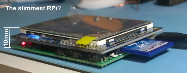
[Colin], AKA [Domipheus], was working on a project to monitor a thermostat with a wall mounted Raspberry Pi and a touchscreen. Simple enough, but the Pi has a problem: The plugs are all around the perimeter of the board, and with a TFT touch screen shield, it’s a bit too thick to be wall mounted. What followed is a hack in the purest sense: [Domipheus] removed and relocated components on the Pi until the entire Pi/display stack was just a hair over 10mm tall.
A Raspberry Pi Model A was used for this build, meaning the Ethernet jack was gone, and there was only a single USB port to deal with. Still, the highest components – the RCA and audio jacks – were too tall and needed to be removed; they weren’t going to be used anyway.
After these components were gone, [Domipheus] turned his attention to the next tallest parts on the board: fuses, caps, and the HDMI port. For fear of damaging the surrounding components when removing the HDMI connector the right way, this part was simply hacked off. The large tantalum cap near the USB power connector was removed (it’s just a filter cap) and the large protection diode was moved elsewhere.
Slimming down a Pi is no good without a display, and for that [Domipheus] used this touchscreen thing from Adafruit. Things got a little complicated when the project required the ability to remove the LCD, but you can do amazing things with a DIP socket and a file.
The end result is a Raspberry Pi with touchscreen display that’s just a smidgen thicker than a CD case. It’ll fit right up against a wall in its repurposed enclosure, and the end result looks very professional.
[Thanks Luke via reddit]


I appreciate the hack. But if you were committed to the Raspi, wouldn’t the Compute be a better starting point?http://www.raspberrypi.org/documentation/hardware/computemodule/
A Compute module might make it thinner if you put a SODimm socket on the LCD, or made the footprint bigger. Three PCBs is going to be thicker unless you get even more creative. Custom PCB or lots of really tiny wires would make it more difficult than this build.
after initially writing a different reply, i decided to actually read the source article/writeup, and i think its safe to say ‘a project to monitor a thermostat with a wall mounted Raspberry Pi and a touchscreen’ is not really what the goal of the project is.
The compute module with the IO board is pretty pricy ($200 for the module and io board) and building on your own IO for the module would be a pain (I can’t find just the modules for sale either). It’d be a lot of extra effort for a very small gain, 10mm is pretty thin to start with.
I didn’t realize the bare compute boards scarce. I’m guessing the combination is considered a development kit, and the bare compute board is only available with a quantity order direct with the foundation. If so, it’s not really very friendly to hacking.
Hey folks, creator ‘Domipheus’ here. Thanks for your comments! The reasons for not using the compute module have mostly been covered by others. Just a) I don’t have one and b) creating the sodimm interface would take quite some engineering. I’d rather not solder directly onto the sodimm pins, despite the butchery in my build log above. Having some unpopulated GPIO on the compute module would have been ideal for me!
Yeah, I was looking closer at the Compute after I wrote my comment. It looks like the compute missed the boat if they were going for the hacker market: sodimm edge conx. requiring a sodimm socket, 100 lot quantities and still pay more than for a model A. I understand your choice. I just assumed that the Raspi org had produced an embeded form factor Raspi like they advertised. I’m not sure what they ended up with, but I don’t see it popping up in any of my projects in the future either.
Props. to you on your project [Domipheus].
This is very impressive. I’ve taken to substituting parts to lower board profiles, but this is a lot more ambitious than I’ve ever done. With practice, it’s pretty easy to do with a hot air rework gun.
Someone needs to build a RasPi GPS with this setup.
They could, but you can already get mobile phones in this size, with GPS plus everything else. I suppose this has the advantage of customisation.
Actually can you get real GPS on an Android? There’s Google Earth, but that relies on a connection to Google for the maps. Is there anything you can get with a load of maps you can store on SD card, so it’d be useful outside the signal area?
Yes, there are a few. I like OsmAnd, which uses the Open Street Maps and can download full countries and provide directions.
I use both OsmAnd and Maverick. both cache maps on your card. Osm has the advantage in that you can download prepackaged regions, while with maverick you have to view the area manually and in the zoom ranges you want before going off line.
Maverick’s BIG advantage is a large of map sources you can view, each tailored to specific uses. Current version lists 23 sources, plus the ability to add more or user generated. MapQuest, OSM, Microsoft, Nokia, Wikimedia, KikeBike, Ordnance surveys, OS Explorer, Yandex… geocaching, googleEarth, share your location, tracks, waypoints.
Maverick is by far the best mapping tool anywhere.
Full disclosure: I am not in any way associated to Maverick, paid by them, etc. Heck I dont even pay for the full version (the free version is already amazing).
I live in a foreign country. Maverick does a MUCH BETTER JOB of renderig Kanji and or converting to English. When rendering roman letters from Kanji, OsmAnd assumes its Chinese, not Japanese. VERY DIFFERENT pronunciations. Maverick usually handles it much better.
Google maps can cache maps as well since at least a year or two. There is a size limit though.
I had initially thought [Dromipheus] had flipped the screen to run on the reverse side of the Pi but then I noted that even the SD card holder had not escaped modifications!
My only wonder is how hot the main chip gets (although [Dromipheus] does say it’s supposed to be a low power usage).
for the next project, consider to use a “Raspberry Pi Compute Module” instead of a normal rasp
Get a micro sd card converter and that pokey bit out the side disappears! :-)
Specifically the half-size adapters. I have a crapload of them because of Pi work. Unfortunately I have nothing else to use them for.
I think the only reason those short microSD adapters exist is the RaspPi A & B. I don’t know of another product that depends on an SD card to operate, yet leaves the card so exposed and vulnerable. It was a ridiculous situation.
Since he started soldering here and there, I think a good hack would be to directly solder a micro SD adapter in place of the SD connector.
Must admit this is just pure lazyness. I knew the SD cards I use have a small flash chip and the rest is wasted space, so I just cut away half the SD card so it’s flush with the outside :P
Wouldn’t this kind of setup really damage the lifespan of the RPi? I mean its core puts off quite a bit of heat.
It’s something I’m keeping an eye on and experimenting with. Ive tracked temperature whilst downloading from WiFi and it doesn’t get above 45C, still I’ve made some silly heatsink prototypes to see if they make any difference (see https://twitter.com/domipheus/status/489899724112416768).
I wonder if you could get some kind of heat pipe into the same form factor as that bundle of copper wire?
I had a quick look, but couldn’t find anything that was readily accessible, sadly.
you realize this broadcom chip was designed for phones, right?
>you realize this broadcom chip was designed for phones, right?
It still gets crazy hot. That’s why there are kits with the right size heat sinks available.
It consumes a watt, tops, and that’s with the graphical core blazing as well as the CPU.
If you’ve seen the heat sinks, I have, they’re utterly tiny! About 1.5cm square for the big one, then a 1.5x1cm, and 1x1cm. Wee little aluminium stubs. Not sure what the max temp for the Broadcom chip is, but usually chips can take over 100C.
Using the Pi, with the heat sinks, at 950MHz, they don’t even get warm.
Just a small note, the input capacitor he removed is an aluminum electrolytic not a tantalum.