Audiophiles tend to put analog systems on a pedestal. Analog systems can provide great audio performance, but they tend to be quite costly. They’re also hard to tinker with, since modifying parameters involves replacing components. To address this, [tshen2] designed the DSP 01.
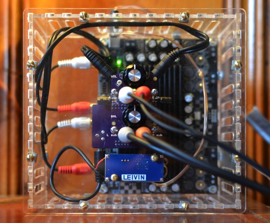
The DSP 01 is based around the Analog Devices ADAU1701. This DSP chip includes two ADCs for audio input, and four DACs for audio output. These can be controlled by the built in DSP processor core, which has I/O for switches, buttons, and knobs.
[tshen2]’s main goal with the DSP 01 was to implement an audio crossover. This device takes an input audio signal and splits it up based on frequency so that subwoofers get the low frequency components and tweeters get the higher frequency components. This is critical for good audio performance since drivers can only perform well in a certain part of the audio spectrum.
Analog Devices provides SigmaStudio, a free tool that lets you program the DSP using a drag-and-drop interface. By dropping a few components in and programming to EEPROM, the DSP can be easily reconfigured for a variety of applications.


Eh. Not a hack.
But it’s certainly a tool. I guess it has that in common with you. Go home.
lol, owned
Well I’m looking forward to your hackworthy contribution then. Otherwise…
Advertisement for ADI
Hackaday in selling out
He designed and built his own PCB, how is this not a hack?
nice advertisement, interesting product!
I hope he used oxygen free plastic
…because?
I think that was a joke in reference to “oxygen free” copper speaker wire sounding “better.”
Damnit, now I’m slightly less blissfully ignorant of audiophile religion.
I thought it was so that stranded wire doesn’t oxidize in the insulation, messing up conductivity between the strands.
It should be noted that it uses a nice 28 bit ADC/DAC
hi! it actually uses two 24-bit ADC’s and six 24-bit DAC’s. the DSP core itself runs on 28/56-bit math (single/double precision) to provide 4 bits of digital headroom over the 24-bits from the data converters. this lets you have up to 2^4 = 16 internal digital gain without causing a buffer overflow!
That’s still 144dB of dynamic range… It could be useful if you want to record impulse responses by firing a starter pistol, but then you would want four input channels fed by a sound field microphone. For output we are basically talking about sonar.
If you’re doing either of those I’d love to know. Way cool tech. =)
If you like this stuff, there are far more interesting hacks/products appearing on diyaudio.com. Apart from the fact that most people there build their own amplifiers and speakers, there are lot of people hacking up DSP systems, occasionally from chips (especially ARMs with high speed serial ports that can be configured to do I2S) that aren’t explicitly intended for audio/DSP purposes.
Analog systems tend to be costly? Analog audio components are always much, much cheaper than digital dsp driven components. Usually by an order of magnitude or more. Having a high quality ADC and DAC alone is complicated and expensive, and even the most basic DSP is a lot more expensive than simple analog circuits. That sentence is completely nonsensical.
hi!
i used to think that too, but times have changed. the noise and distortion performance i usually shoot for require really expensive op amps – we’re talking about very high slew rates
hi!
i used to think that too, but times have changed. the noise and distortion performance i usually shoot for require really expensive op amps – we’re talking about very high slew rates, gain and bandwidth. these cost easily $6 per quad package, and they will still have a higher noise floor than a well made DSP. a good stereo analog signal professor can easily cost $200 once you add in the cost of precision resistors and capacitors and the higher cost of the larger PCB. analog is also inflexible, so you will be paying more to add functionality over time. and you will need a bipolar power supply, and that costs money too. the BOM for my DSP board is about $50. it would be at least five times higher if done in analog, and require way more assembly time, and discourage tweaking. Plus I get to use digital-only techniques such as time delay and nonlinear correction.
LME Ops are usually not worth their money unless we’re talking about audio ANALYSIS gear (like a THD or noise analyzer. because there you really need that near-0 THD with ultra-low noise.). Stick with the usual NE 553x ops ; the music you’re listening to has been going through at least a dozen of them anyway.
They are if you buy the oxygen free crap and all that other unobtainium stuff.
There is bad analog and bad digital both. Same for good.
But the project has potential at 24/??, certainly more than a simple x-over.
DSP vs. caps and coils.
Once again a sub woofer is not a single regular woofer used with N mids and tweeters in a multi-channel system. That would be mono bass in a “stereo” system. With a sub you have as many woofers as mid and tweeter channels. Irrelevant of the number of channels of amplification. Bi-amping may be one good use of this design.
He kinda of ruined some of the noise floor for using $2 Chinese switch mode power supply drawn from the amplifier to power the DSP. They are not know to put in additional filters nor use good quality capacitors.
In a buck configuration, the input filter is critical as the input side sees a discontinuous chopping waveform. That can get injected back to the power amplifier power supply. The output current waveform is continuous, but still want to have a snubber as they tend to have a high frequency ringing due to parasitic. Probably should use some additional RC filtering on the output side and a better LDO with PSRR at the switching frequency of the power supply. If not carefully treated, some of that can alias into the audio range.
I wouldn’t trust the 50dB PSRR of the DSP too much as they only give you a single number at 1kHz and not even show you a plot vs frequency of the typical part. You basically have no clue how quickly it folds at higher frequency.
Also have to think about grounding of the setup. Switch mode supply with thin input wire where there is going to be huge discontinuous switching waveform… That is asking for trouble as some of the return current might decided to go through the audio grounds to the amp.
hi,
the SMPS was an intentional move on my part. the SMPS regulates from 24V to 5V, and is followed by a super nice linear regulator which goes from 5V to 3.3V. this was not done trivially, and some math and scope-measurement was involved. the SMPS also operates at a high enough switching frequency that its noise is not audible, and does not alias into the audio range. i can report that the DSP is super quiet in operation, and the noise floor is dominated by the quad-channel amplifier.
see TI’s $0.60 TLV70033 LDO. Very wide bandwidth PSRR, low noise LDO.
http://www.ti.com/product/tlv70033/description&lpos=See_Also_Container&lid=Alternative_Devices?keyMatch=TLV70033&tisearch=Search-EN
Way to go tshen on getting it all together and built.
thank you very much Bill!
This is really wild. I’m impressed, tshen. Any latency issues with this if used in a production setting?
hi rob!
the latency of this DSP is in the single-sample range, i.e. below 0.1ms. i’m actually designing a set of really wild studio speakers around it as my next project :)
i’ve also been giving it multiple ‘modes’ to dynamically change the bass cutoff – for example, simulating a small speaker with a bumpy 100Hz bass tuning. this is another production feature – you can simulate how your track will sound on various kinds of speakers (by going through the various modes), without having to actually play it on a bunch of different speakers.
Whoa. That’s wild. The simulation option is a fantastic idea. You’ve got something marketable here.
Yup, I’m pretty impressed with this too. I was looking at DSP about 20 years ago (reading about it), trying to figure out how to create x-overs for 3 or 4 ways without phase issues but DSP technology was way out of reach for us back then. This looks like a good reason to clear off my workbench and heat up my iron again.