My introduction to electronic manufacturing was as a production technician at Pennsylvania Scale Company in Leola PA in the early 1980’s. I learned that to work on what I wanted to work on I had to get my assigned duties done by noon or thereabouts. The most important lesson I had learned as a TV repairman, other than not to chew on the high voltage cable, was to use your eyes first. I would take a box of bad PCB’s that were essentially 6502 based computers that could count and weigh, and first go through inspecting them; usually the contents were reduced 50% right off by doing this. Then it was a race to identify and fix the remaining units and to keep my pace up I had to do my own desoldering.
It worked like this; you could set units aside with instructions and the production people would at some point go through changing components etc. for you or you could desolder yourself. I was pretty good at hand de-soldering 28 and 40 pin chips using a venerable Soldapulit manual solder sucker (as they were known). But to really cook I would wait for a moment when the production de-soldering machine was available. There was one simple rule for using the desoldering station: clean it when done! Failure to do so would result in your access to the station being suspended and then you might also incur the “wrath of production” which was not limited to your lunch bag being found frozen solid or your chair soaked in defluxing chemicals.
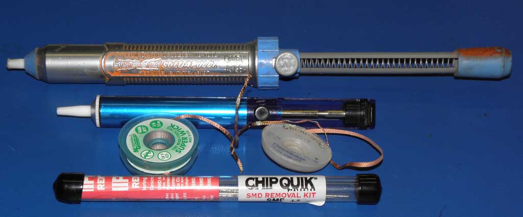
One thing was that I could never afford was an automatic de-soldering station… until now. I have found that there is a wide assortment of stations available from overseas and through eBay that mimic their production quality brethren and I demonstrate here a vacuum based desoldering station, an Infrared Heat based station, and some other tools such as hot air and desoldering tweezers.
Vacuum Desoldering
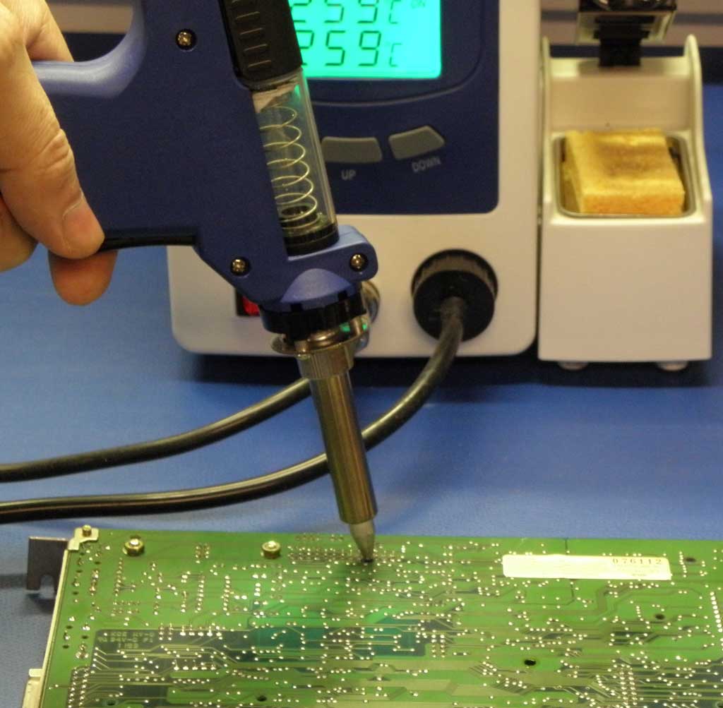
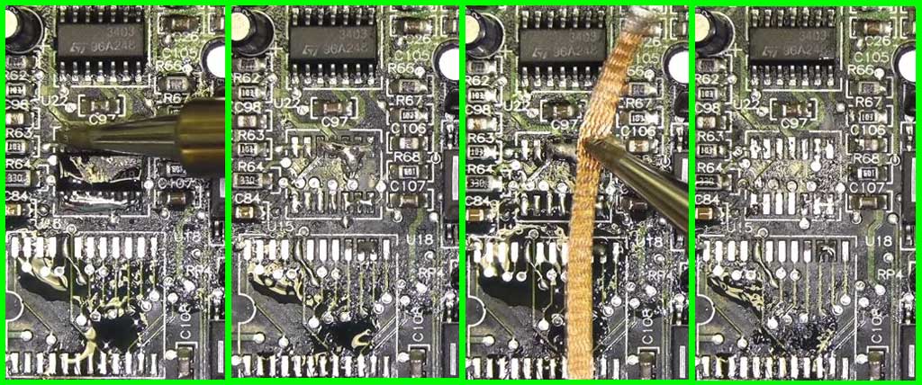
The vacuum based through-hole desoldering station consisted of a soldering iron with a hollow tip and body which leads to a glass tube capped by a filer at one end which is also the end the vacuum is applied to. The trick is to heat up the whole solder joint (I use an ample amount of flux to assist) and then start the vacuum by pulling the trigger. During this time I am also wiggling the soldering iron tip in order to break the component pin free from the wall of the hole or plate-through. Done correctly both the PCB and the component being removed are reusable.
Infrared Desoldering
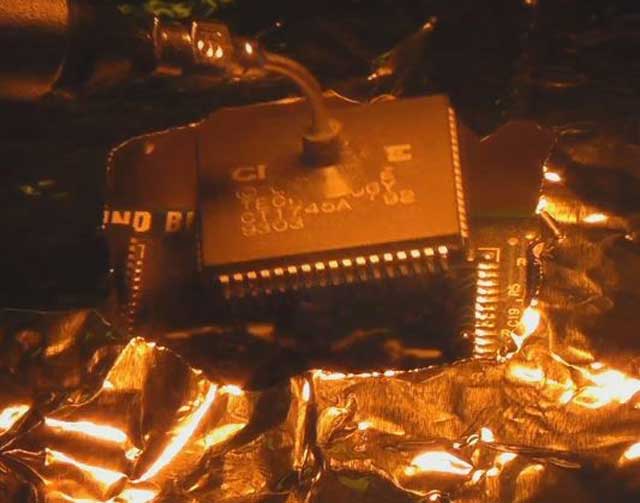
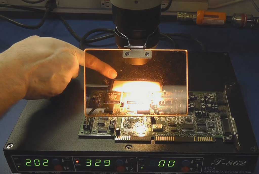
The infrared based system, referred to as an Infrared Welder by the manufacturer, can ultimately heat a smaller area to a hotter temperature than hot air, or so I believe. To mask off the surrounding area for hot air you need to keep your airflow low and redirect it away from the rest of the PCB. To redirect Infrared you use the reflective properties of aluminum foil. It’s then mostly a matter of firing up the fume fan and having the patience to wait for the direct heat to do the job. Again a judicious use of flux helps.
Hot Air Desoldering
Hot Air is similar in that flux helps, fumes and smoke may be present and you have to have the patience to wait for the part to come fully loose — half loose doesn’t cut it. To this end I recommend a hot air holder, a fume fan and an egg timer. If you don’t have an egg timer I am sure there is an app for that somewhere.
Desoldering with Chip Quik and an iron
I have found The quickest way to desolder SMT without investing in any of this equipment is to use a product like Chip Quik which lowers the melting point of the solder metal when mixed with it as it allows a soldering iron to melt the entire chip’s footprint simultaneously allowing it to be removed.
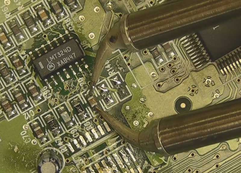
Desoldering Tweezers
Finally the tweezers. You don’t need these… I certainly didn’t. But what the heck, there is a certain cleanliness of motion that when removing a part with two pins to use what essentially is two soldering irons. Oh yeah… lots of flux first.
Back to the story: Four years later I had worked my way up to being one of the lead design engineers at the best home computer company of its day. We had hard deadlines like the CES show in Las Vegas which would inevitably occur while we still had 3% of the product to finish. It’s a safe bet that being able to de-solder quickly and more importantly without damaging prototype chips and boards that were irreplaceable, was an indispensable skill at 2:00AM when any technician in their right mind would be home in bed instead of pulling chips for the engineer whose bed was an air mattress in his office. We never missed a CES.


The biggest mistake I see rookies make when they are desoldering is they act like there is some kind of prize awarded if they can manage to take burnt out components out whole, and intact. That stuff is garbage! Once you get a bad part off a board you are only going to throw it out anyways. So who cares how good it looks in the trash can? What I was taught to do was to cut the parts out manually, with clippers, then desolder every lead individually. Only having to deal with a single lead at a time makes things a lot simpler. Component salvage is one thing, board re-work is something completely different. In each the value of different items is reversed. One’s methods should reflect that accordingly.
My 2 cents:
It’s not worth cutting out if you cant do it ‘nicely’. Physical damage to the pads should be avoided.
How are you going to damage pads cutting leads? I suppose it is possible, but come on. I am not talking about surface mount, I don’t work on that.
We remove dead SMT chips by running a scalpel down the legs, then you have a row of individual legs to desolder rather than trying to heat up all of them at once. Granted you need to take care & not damage the board traces underneath (or know there’s nothing underneath that could be damaged), but it does make life much easier.
I built SMT boards. Thank God I never had to fix one though. I got out of the racket before that.
I bet you could make a jig for a Dremel that you could run down the side of the chip at the right depth to cut all the leads and not touch the board.
That is what my old beater soldering iron essentially does. I just nuke it from outer space with the tip of that badboy and pull the whole melted blob off leaving clean pads ready for anything. It is probably a bit more shoot from the hip than this crowd would like, but as long as you know how your iron works and have a steady hand you can do the same. I wouldn’t recommend my method for expensive things but those projects tend to be for clients instead of me just getting something going again.
Fingernail clippers are always a handy tool to have on the bench as well for snipping leads and snipping smd resistors off of boards ;)
While we are here, I’ll just go ahead and say how much I dislike soldering braid. Almost rather use rogue bits of wire than the real deal. I am sure others have great success with it but it just frustrates me more than anything. Same with flux; I never use the stuff but that is because it is gross and I have just never needed it really. Ticks me off when I go to desolder some old school thing and the board is pretty much iced with it so that you have to cook a layer off. I understand it was part of the process back then but it just sucks to deal with now. Usually makes me nauseous and surly lol.
Best of luck to all of us snagging parts and keeping things out of the landfill :)
This is exactly what I was going to say. I’d use an xacto knife to slice off the pins – often even if the part was still “good.” A prototype PCB is priceless compared to a 15 cent… comparator. And a lot harder to replace.
What happens when the part costs $100 or more?
Depends on the project. Most $100 parts are BGA’s, so this wouldn’t work. But if you’re up against a deadline and have only a handful of prototype cards, it might be worth $100 to not destroy the PCB. You’d have to make the call on a case-by-case basis.
spoken by someone who never used hotair? why bother risking physical damage to the board or neighbouring components if you can simply heat something up in 10 seconds and lift it up whole?
Cutting leads applies a force to the land and damage it, often in a way that isn’t immediately visible.
Maybe with SMT. I should have specified I was talking exclusively about through hole parts with pads, not lands. Throw broken SMT garbage out. Re-working that stuff is a whole different ballgame that requires specialized equipment. Well, I suppose it doesn’t require it, because plenty of hacks manage without it. Typically I favor the pro methods though. Which is one reason I never got involved with SMT myself.
Same thing with pth, even worse since the pins are bigger around and therefore grow more when snipped. Here’s a good example of a pth land that has dislocated from its trace due to applied force: http://i.imgur.com/Q9QMi04.jpg http://i.imgur.com/ZtHJCxD.jpg Note that the break is tiny, even hard to see under SEM. The pad isn’t even visually lifted, but its enough.
As a hobbyist, working with SMT is so much less time consuming and lets you spend a lot less money. For instance, each time I get a new resistor value, I spend a couple bucks and get a thousand of them. The boards end up being smaller so lower cost there too.
Guess it’s time to invest in a mic stand, and learn to sing to justify the purchase. ;)
I’ll admit, I’ve come up with an altogether more… gruesome way to remove components from a PCB. It’s a way to remove the PCB from the component, actually. – On a Saturday I wanted some discrete power components off a CRT TV’s PCB, and lacking patience I went for a pair of pliers and started to break off pieces of the PCB. The components came loose and then I could just heat up the legs one by one to clean them. Since I held on to the components with my fingers I could not heat them up so much that there was any chance of damage.
I recognize that we’re talking about the opposite problem here. – I’m only recently getting back into electronics and I find it fun, liberating to have a completely disposable selection of random components, so I don’t feel like I’m wasting resources by letting them be consumed in cruel and unusual experiments. I leave components with bits of PCB stuck to their legs and just archived them by basic type so they don’t take up much space until the time I might find a use for them.
I think of this as a resource similar to manufacturer samples, but faster and entirely more Discordian.
I’m a fan of cutting leads prior to desoldering too. A Dremel works great, and causes no stress on the pads. Just be careful, go slow, and let the tool do the work.
Picture what is happening when you snip a lead. You apply shear force to the middle. The metal deforms and the lead gets longer. It keeps getting longer till the tool cuts all the way through. If you are cutting back side leads that aren’t connected to anything, no problem, only one end is fixed. But when you cut a component side lead, both ends are fixed. One against the IC which is held in place by all the other leads. The other by the single pad. Guess which side moves.
Darnit, I need to delete that comment, didn’t notice the dremel part of the reply. stupid stupid stupid.
I’d not recommend a Dremel. It’s *way* too easy to lift pads and traces right off a PCB with one.
I know… in a moment of impatience I tried it instead of desoldering pins the proper way. It took twice as long to repair the traces as it would have taken had I not used the Dremel.
dremel? thats BRILLIANT, now you covered your board (top, between the leads, under components) with small shards of electrically conductive material.
My thought exactly!
If it is a masked board what is your point? Part of board re-work is the word work too. It might take a bit of work to clean things up but it comes with the territory.
My thoughts exactly
I have had problems with high frequency vibration caused by rotary tools with solid state components. I have had that vibration destroy ICs internally. I can’t tell you exactly what it did, I imagine it broke the connecting wires from the die to the wire frame. I have only seen it in a few rare instances too, but I’ve seen it happen.
This.
I’ll never use a dremel on a PCB again.
I’ll admit, I’ve come up with an altogether more… gruesome way to remove components from a PCB. It’s a way to remove the PCB from the component, actually. – On a Saturday I wanted some discrete power components off a CRT TV’s PCB, and lacking patience I went for a pair of pliers and started to break off pieces of the PCB. The components came loose and then I could just heat up the legs one by one to clean them. Since I held on to the components with my fingers I could not heat them up so much that there was any chance of damage.
The best tip he gives it to use flux, it would be my first second and third tip. Flux magically makes desodering easy.
Flux meh, We’d run over everything with flux solder, and that works. I’ve dropped flux on too, it isn’t the same.
Amen. This is what I tell newbies: If the solder isn’t smoking anymore, it’s run out of flux and is now your enemy. Add flux, take enough time, don’t be afraid of the iron, add more flux.
Your comment made me laugh – positively of course. I’ve remembered my firs steps in desoldering – it was a harsh battlefield :)
Achievement: You found flux!
Soldering skills +3db
Regarding the tweezer desoldering: those things are really bulky. What i like to do instead is take my soldering iron tip an place it across both pads of my SMT caps or resistors, then just add solder to both pads and the part will pop off. You’ll have to clean up the pads afterwards, but it is a great method to remove 0201 sized components underneath a 2000+ ball BGA.
ah all these old soundcards. That was actually one of the earlier Sound Blaster 16s. And that Opti one I could use to fix a laptop whose soundcard throws bluescreens as soon as you install the driver (win95). In Win3.11 it works for a few minutes and then gets unstable, DOS works for up to half an hour…
in no particular order, metcal desoldering talons , metcal desoldering gun (ebay), hakko 808 for portable, hakko 772d for ESD safe, underboard preheater, chipquik or the zeph lowmelt desoldering sticks, and zephtronics flux. the world is your oyster.
The low melt is definitely the easiest to do, much harder to lift a pad too,, also easy to clean up.
typo, hakko 472d for esd safe..
MANY moons ago I was working for one of the national labs-the Advanced Photon Source near Chicago. Think of it as a “Mini Fermilab” accelerator designed to produce x and gamma rays.
It contained several thousand DC and ramped DC (Triangle-wave output) power supplies from about 100 watts to well into the the megawatt range-so we fixed a lot of power supplies!
They brought in a group to teach all of us professional PCB repair techniques (as well as IPC repair/inspection standards). All of the workstations in the mobile home (ten in all) had CAL rework stations. These were cool because they used induction heating of the tip and were at temp and ready to use in seconds-no matter the size of the tip.
And yes, ever since then my kit always included several sizes of solder and wick, a bottle of flux and Chip Quick…
Excellent video. I really need to get myself a preheater. BTW, the drag method with a braid will absolutely kill small lands, such as 0.8mm BGA pads. You need to cut off little pieces of braid and hold them with tweezers, press down softly on the pad and lift slowly. …for each damned pad. Otherwise you’ll be learning to use the circuit medic replacement lands.
yeah i dislike using braid for this reason, i’ve dragged off more pads with braid than anything. Also takes a bit more heat since you’re heating the braid too. mostly i just use it for bridges.
The only time I have ever seen braid be useful is for doing foil clean up after a part is removed. Other than that braid is so spotty for me I tend to not consider using it today. Braid is perishable too. There is chemical on the braid that does not always last forever. Powder flux? Something on braid that can kind of not be so good with old stock. Plus there is a lot of technique when it comes to using braid effectively, like clipping it at an angle. There is a lot of technique with using braid I suppose. For foil clean up I think braid is great though. For sucking solder out to remove components, not so much. I’ve seen it do that, but not enough to count on it.
you can just dip old braid in flux, works for me even with old shitty chinese braid
Little pieces of braid, huh? Never thought of that, sounds worth a try. Applying some liquid flux directly to the braid helps too.
That braid was a little big but sometimes you use what you have on hand and adapt. :) Having video equipment all over the lab is a sure fire way to lose something, in this case I threw out some extra flux to try and help with width of the braid.
++ on braid taking off pads
Another thing missing in the video is TEMPERATURES. Not a peep (or did I miss it?) about proper temperatures for solder type or chips and pcb safety.
Too much temp and pads will vanish/stick to soldering iron. Using PBfree temps for PB GPU/Chipset bga and you will destroy it (it will bridge inside). Too little temp and you will rip pads off. Heating for too long and you will cook something. Heating too quickly and you will crack something. Heating one side of multilayer pcb and you will warp it.
Patience also helps, couldnt watch that braid part, Bill almost cleaned few passives off. Trust me – its not fun hunting for a photo of a similar pcb to figure out what got ‘disappeared’ by accident during repair :/ Posts asking for a macro picture of a part of pcb for that very reason are the norm on service forums.
this ‘I had to solder over 3 video cameras and couldnt see clearly’ is a standard dog ate my homework excuse, Dave Jones uses same one every single time :D You are trying to show something – either show it properly, or dont show it. There is no point showing something bad or sloppy. Its like a car instructor smashing into few traffic cones and saying ‘oh, but It was just a quick demonstration, trust me I know how to do it properly, its your turn now’. How is anyone supposed to learn anything from that?
Again, I highly recommend you want some of the clips from this channel
https://www.youtube.com/channel/UCzlXwR8hC2cY2r_TbME3ORw
Difference is they are really fixing something and video is just an addition. Their biggest concern is following correct procedures, not operating video equipment.
Its not like you are on some time/words limit.
This is a different format with different goals, in this case a very quick exploration of several techniques as an introduction to their capabilities:in 8-10 minutes.
Today we’re offering a double your money back refund if you did not care for the presentation. So here’s nothing. Now get lost with it!
Don’t use little pieces of braid. Use a longer piece of braid, tacky flux, and a blade tip to remove the solder in one smooth wipe. You can get blade tips from 5mm up to 30mm wide. Get a length of braid, dip it into the tacky flux and then, using the blade on top of the braid, wipe the BGA pads.
Love the technique. I have invested in a ZD-985 and it works like a pro. Even the $20 heat guns from Harbor Freight have worked just as nicely for many a repair. My electronics instructor used to use the old “pocket butane torch” to get the components off the board. As always, very interesting and informative videos, Bill. ;)
I highly recommend 1servicecore YT channel for some practical soldering/desoldering videos from a real life service center
https://www.youtube.com/channel/UCzlXwR8hC2cY2r_TbME3ORw
They have everything, big ass bgas, removing shorts inside 12 layer boards, fixing easy stuff (caps/ batteries/fuses), finding broken transistors/drivers, flashing firmware, reconstructing scraped 6mil tracks. You name it they got it.
And so’s your mom.
To remove all the SMD from a board, I like to use a big air gun (the ones you use to remove paint, not the ones for electronics), I just incline the PCB and let all the SMD sail their way out of it. I don’t know anything faster and you just have to pick up the components once they’re cold. You can also do mostly the same for through-hole devices by heating the back of the PCB and using tweezers to pull the components out.
We had a tech in production (1980) that didn’t realize that we had 175 and 350 degree heatguns. He turned the 350 degree on one a board worth a $1000 on the street and then took a break or something. We he came back the labels on the eproms were actually charred at the corners and the sockets had curled leaving the pins soldered in. He came running up to me to declare I must have fixed the heatgun wrong.
That was a really nice video, nicely made and told. I’m mostly using hot-air method, so I shall buy microphone stand ^^
If I was stranded on a desert, and I could only bring three items, Chip Quick would definitely be one of those items.
Beware Solder Tweezers!
The *original* tweezers were primarily for connecting wire to pins [or sockets] on plugs. As such, they had a foot-activated switch, and heated by passing a Large Current between the tweezer points.
http://imshopping.rediff.com/imgshop/800-800/shopping/pixs/4463/2/275._10pcs-d-sub-9-pin-db9-female-solder-type-socket-connector.jpg
The use of a large current may have unintended side-effects, depending on whether you are de-soldering resistors, diodes, or capacitors.
Found this on Silab site: AN114: Hand Soldering Tutorial for Fine Pitch QFP Devices
http://www.silabs.com/Support%20Documents/TechnicalDocs/an114.pdf
It is unusual that a vendor has a tutorial showing desoldering and soldering tutorial with a temperature controlled soldering iron for a QFP part these days.
For desoldering, they inserted a wire behind the pins, anchored on one side. As you heat up the pin, you tug on wire and the wire lifts up the pin. I used a similar technique at one point.
here is pretty sexy SMD tutorial / show piece by Pace/Metcal reseller
https://www.youtube.com/watch?v=tg8ZcwrGrEU
I especially love the lighting, lack of clutter on the desk and pace. There is no rush, no shaky hands, sex on a stick.
That’s a like vacuum cleaner for solder. :)
Here is the guy that does miracle work at Shenzhen Hacker Camp with hot air tool:
https://www.youtube.com/watch?v=LQjV2APK9zQ#t=40
here is the IPC level 3 instructor that does amazing drag soldering job
https://www.youtube.com/watch?v=5uiroWBkdFY
Hey Bil,
Long time since I worked at Pennsylvania Scale! I remember fixing those PCBs and customizing 6502 assembly language.
Thanks for the walk down memory lane.
Jeff Dombach
Looks like you got there right after I left for Commodore? Yeah I might have filched Hedley and Fish also. >:) I figured if I mentioned the company, right in the heart of Amish country, someone would identify with it. And everyone knows Nauman…
Hot plate and a fry pan full of peanut oil ( doesn’t burn) and a tweezers work great. You can put em on and take em off.
I think someone forgot to tell peanut oil that doesn’t burn :) However it does have a high smoke point making it useful to cook the holiday turkey in a deep fryer, and the bulk removal of electronic components it appears. However it doesn’t sound like viable method for replacing faulty components though.
I’m pretty sure there is no wrong way to remove components soldered to a circuit board. Save for mucking up the circuit traces when repairing equipment is a goal. Potentially leaving metal filings can’t be good idea. Neither would be destroying components meant to be salvaged with excess heat.
Bil – Thanks for this! Any chance you could also a video on SMT soldering methods for the hobbiest?
is there possible desolder the smd components automatically?
and are there any method to do so if possible?
I know that this is 2022 and my question is really quite dated but still in 2014 when this YouTube video was posted,,,,,
Where in the heck do you get a nice and new not faded and old Tommy Bolin concert TShirt???!!!!!
It makes my mind Post Toastie seeing that shirt while working the infra red….